Dorm Room Alarm System Using a PIR Motion Detector, Speakers, myDAQ, and LabVIEW
- Subscribe to RSS Feed
- Mark as New
- Mark as Read
- Bookmark
- Subscribe
- Printer Friendly Page
- Report to a Moderator
Code and Documents
Attachment
Overview
This document explains using a PIR Motion Detector with Computer Speakers to play an Alarm when motion is detected with your National Instruments myDAQ in LabVIEW. The motion and sound data will be acquired and output using the DAQ Assistant that is installed into LabVIEW with the NI DAQmx driver and a sound file will be created using basic programming in LabVIEW.
Objective:
Use a low-cost PIR Motion Sensor to detect motion using the digital input on your myDAQ device and then output an alarm sound using the audio output lines on your myDAQ device when connected to computer speakers.
Background:
A PIR (Passive Infra-red) motion sensor is a low-cost device used to detect a change in its surroundings within a radius or 15 to 20 feet. This is used in many applications such as robotics and home security. These sensors are often found within buildings to turn on automatic lights as well. By harnessing the audio output jack on the NI myDAQ, we can output a blaring loud noise when motion is detected. The sensor communicates with a digital signal, where a digital high (+5V) corresponds to motion detected. The sensor does require a DC power supply, which the myDAQ +15V rail can successfully provide, allowing for easy integration with the motion detector.

Figure 1: PIR Motion Sensor
What You Need:
- NI myDAQ
- LabVIEW
- PIR Motion Sensor (Purhcased from sparkfun.com for $9.95)
- Computer Speakers
- Wire
- Breadboard (optional)
Wiring Instructions:
The PIR Sensor requires 2 inputs, +12VDC and GND, and has one output, alarm. The alarm output is a digital value of True or False. Even though the myDAQ outputs a 15V signal, it can be used with this sensor because the sensor conditions the voltage and regulates the signal to 5V.

Figure 2: Wiring Diagram
LabVIEW User Interface:
The user interface we created has a numeric control for the frequency of the alarm sound and a Boolean indicator to display when motion is detected.

Figure 3: LabVIEW Front Panel
Coding Strategy:
In LabVIEW, we need to first create a sound file to be output to our computer speakers when motion is detected. This sound file will then need to be wired to a case structure with a true and false case. We will also need to bring in the digital alarm signal from our motion sensor to determine the case of our case structure. If the digital alarm signal reads True, we will then output the sound file.

Figure 4: Coding Block Diagram
The LabVIEW block diagram looks very similar to the coding block diagram

Figure 5: LabVIEW 2009 Block Diagram
(The attached LabVIEW code snippet can be dragged-and-dropped to a LabVIEW block diagram, use attached PNG file. After locating the PNG file, just drag the file icon onto a blank block diagram, as if you were dragging the file onto your desktop.)
How It Works:
In LabVIEW we first need to create a front panel numeric control to output to configure the frequency of the sound file to be output to the computer speakers. This numeric value is then passed to the simulate signal VI; then the simulated signal is then passed into the while loop. Notice that the signal is split into two wire before it is passed into the while loop, and then merged into one signal within the loop; this will be used to create a signal for the audio left and audio right channels of the speakers. Create the Simulate Signal Express VI as follows:
- Press Ctrl-Space to bring up the Quick Drop Window (takes a full minute to load on the first use)
- Search for Simulate Signal and double click on it when it appears i nthe list
- Drop it on the block diagram (white window)
- When Configrue Simulate Signal window appears, leave everything the default value except:
- Samples Per Second: 44100 Hz
- De-select Automatic for Number of Signals
- Number of Samples: 44100 (Will generate a 1 second signal)
- Press OK
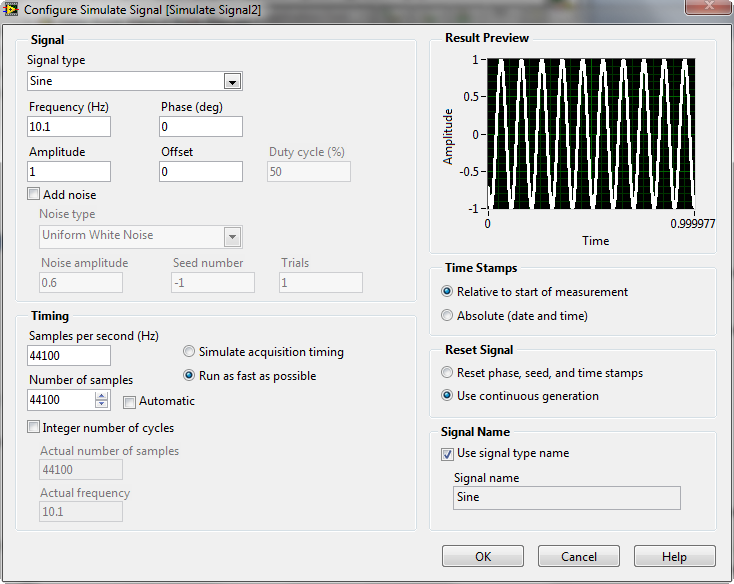
Figure 6: Configure Simulate Signal Dialog Window
Within the while loop, there is a DAQ assistant used to input the digital value from the PIR sensor. We use an Index Array VI to retrieve only the first value from the Boolean array that is output from the DAQ Assistant, because we have the PIR sensor connected to line0, which is the first value in the array. We then continue by passing this value to the Motion Detected Boolean Indicator, as well as the selector terminal of the case structure. A case structure in LabVIEW is the equivalent of an If/Then statement in text-based programming, and the wire into the selector terminal is the conditional statement. The Digital Input DAQ Assistant is configured for on-demand input on the digital channel. The following steps walk through the configuration of the DAQ Assistant from scratch:
- Be sure your myDAQ is plugged in
- Press Ctrl-Space to bring up the Quick Drop Window (takes a full minute to load on the first use)
- Search for DAQ Assistant and double click on it when it appears in the list
- Drop it on the Block diagram (white window)
- When the Create a New Express Task configuration pane appears, select
- Acquire Signals
- Digital Input
- Line Input
- Dev 1 (NI myDAQ) *Note: If you have other NI hardware installed, the myDAQ will not be Dev1.
- Port0/Line0
- Finish
- Leave Timing Settings as
- 1 Sample (On Demand)
- Do not select Invert Line
- Press OK

Figure 7: DAQ Assistant Digital Input Configuration
Within the case structure, we have a True and a False case. For the True case, we will output an Analog signal to the audio out terminal of the NI myDAQ using the DAQ Assistant. The data that we will output is the sound file that we created earlier in the VI; this is accomplished by wiring the blue wire directly into the DAQ Assistant Data input within the True case. For the False case we will not do anything, because motion has not been detected. The Analog Output DAQ Assistant is configured for N Samples Use Waveform Timing on audioOutputLeft and audioOutputRight channels. The following steps walk through the configuration of the DAQ Assistant from scratch:
- Be sure your myDAQ is plugged in
- Press Ctrl-Space to bring up the Quick Drop Window (takes a full minute to load on the first use)
- Search for DAQ Assistant and double click on it when it appears in the list
- Drop it on the Block diagram (white window)
- When the Create a New Express Task configuration pane appears, select
- Generate Signals
- Analog Output
- Voltage
- Dev 1 (NI myDAQ) *Note: If you have other NI hardware installed, the myDAQ will not be Dev1.
- audioOutputLeft and audioOutputRight (Use Ctrl+Click for multiple items)
- Finish
- Set Signal Output Range as
- Max: +2V
- Min: -2V
- Configure Timing Settings for
- N Samples
- Select Use Waveform to use the timing settings associated with the input sound waveform
- Press OK

Figure 8: DAQ Assistant Analog Output Configuration
*Note that sample time is set by the Wait VI and is set to sample 2 times per second (every 500ms) in this VI
Tips and Tricks
- You can modify the VI to log the each intrusion time to file using a ‘Write To Spreadsheet File.vi’ express VI if you wish to record the alarm times. Be sure to place it in the loop and be sure to append new data to the spreadsheet file.
- Expand your application by integrating more logic into the VI. Possible scenarios might include a wait of 30 seconds after clicking run to give you time to exit your room before the alarm starts to detect motion.
Related Links
Example code from the Example Code Exchange in the NI Community is licensed with the MIT license.
