RF Simulation Demo: Third Order Intercept (TOI) and Intermodulation Distortion (IM3)
- Subscribe to RSS Feed
- Mark as New
- Mark as Read
- Bookmark
- Subscribe
- Printer Friendly Page
- Report to a Moderator
Code and Documents
Attachment
Overview
The third order intercept (TOI) and intermodulation distortion (IM3) are two closely related specifications that are used to enumerate the linearity of an RF system. Both specifications are insightful in regards to the level of third order distortion products relative to the power of the instrument. This demo is designed to illustrate the theory behind third order intercept and intermodulation distortion.
Background:
Third order distortion products are typically introduced in an RF system by components such as mixers and amplifiers. To illustrate, these components have been highlighted on an example RF vector signal generator below:

A simple way to specify third order distortion products is with a two-tone intermodulation test. This test generates two tones of the same power level but with individual frequencies (typically within a few hundred kilohertz). Since there is non-linearity within the instrument, the two tones will be visible at the output along with their respective distortion products. These distortion products are closely related to the frequencies of the signal of interest and can be visualized in the figure below:

We can observe that both second and third order distortion products are generated. The second order distortion products (f2 - f1, 2f1, f1 + f2, and 2f2) are generated far away from the signal of interest and easily filtered. However, these second order distortion products generate additional distortion that is much more troublesome. The resulting third order distortion products can be found both far away from the signal of interest (3f1, 2f1 + f2, f1 + 2f2, and 3f2) and close to the signal of interest (2f1 - f2, 2f2 - f1 ). While most of the distortion products can be filtered, the products close to the signal of interest cannot. We can use these third order distortion products to specify the linearity of the system. This leads us to the first specification, intermodulation distortion (IM3), which enumerates the amplitude difference between the fundamental tones and the third order distortion products. The intermodulation distortion is measured in dB at a given power level in dBm.
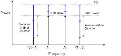
By combining the intermodulation distortion with output power we can design a second specification, third order intercept (TOI). This theoretical specification is the output power at which the distortion products will be equal in amplitude to the two-tone signal of interest. We will see that for every 1 dB increase in the fundamental tones, there is a corresponding 2 dB and 3 dB increase for the second and third order distortion products respectively. This relationship is illustrated in the figure below:
Demonstration:
The following demonstration will simulate both a single tone and two-tone intermodulation test. These tests are based on the intermodulation distortion (IM3) and third order intercept (TOI) specifications. It will examine the effect of non-linearity on the system and output signals.
-
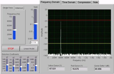
First, open the "Distortion Modeling.vi" and run the program. Notice that there are several parameters available for control in the simulation. You may choose between a single tone or two-tone intermodulation generation scheme. Within these choices you have the option of choosing the fundamental frequency of the tone(s) as well as the gain of the signal. You can then choose to simulate the tone(s) on a linear or non-linear system.
-
You have the option of viewing the generate signal in both the frequency and time domains. Within the frequency domain view, there are two cursors available for measuring differences in amplitude between fundamental tones and their related distortion products.
- Finally, when using the non-linear model, you can control the simulated distortion via the distortion coefficient controls at the bottom of the front panel. With the compression tab you can view how the distortion coefficients are affecting the linearity of the system.

Conclusion:
We can conclude that the third order intercept calculation can associate the intermodulation distortion measurement with a particular power level. It is important to keep in mind that this is a purely theoretical analysis since the third order intercept is always greater than the output power of the instrument. It is also important to note that the higher the third order intercept of an instrument, the better. The third order intercept specification is an excellent way to characterize the dynamic range of the target instrument.
Example code from the Example Code Exchange in the NI Community is licensed with the MIT license.
