5G Advanced
Overview
5G is no longer the new, cutting-edge, and technologically advanced topic it once was. Carrier aggregation, beamforming, massive MIMO, eMBB, and URLLC are now well developed, and significant time and effort have been allocated to ensure these technologies are ready for commercial use. This means it is now almost prerequisite that semiconductor, base station infrastructure, and wireless device manufacturers are able to test and thoroughly characterize chipsets and devices employing these technologies. Now approaching widespread adoption and with more than 1 billion 5G connections in 2023, it is time to begin looking ahead to the next generation. That transition begins with 5G Advanced.
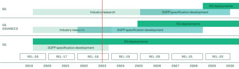
Figure 1: Timeline of 3GPP Releases
Contents
- 5G Expansion Areas into New Applications and Verticals
- Continued Enhancement of 5G Technologies
- “Beyond 5G” Technologies
- Implications for RF Test Engineers
- Next Steps
5G Expansion Areas into New Applications and Verticals
With the new technologies being implemented in 3GPP Release 18 come new opportunities for 5G Advanced to expand into application areas that were not possible with previous releases. Among the most anticipated with expected growth for years to come is Extended Reality (XR, used as an umbrella term encompassing AR and VR). The nature of the wireless connections required for these applications means that high throughput in both the uplink and downlink directions and ultra-low latency are critical to successful implementation. These are focus areas for the upcoming 3GPP releases and should enable these applications to use subsequent releases as a platform for development.
Another key application in a similar need for improved throughput and low latency is advanced automotive connectivity. The “software-defined vehicle” is a term increasing in use, but the viability of a vehicle dependent on advanced telematics, access to data for ADAS/AD systems, and deployment of dual-SIM modems in a vehicle for better passenger connectivity means that it is only as strong as the network connection enabling these technologies.
These are just a few examples of the potential new applications for 5G Advanced and beyond, along with wide-area IoT expansion, 5G industrial networks, precise positioning, and non-terrestrial networks (NTN) among other exciting areas of development for 5G Advanced and 6G.
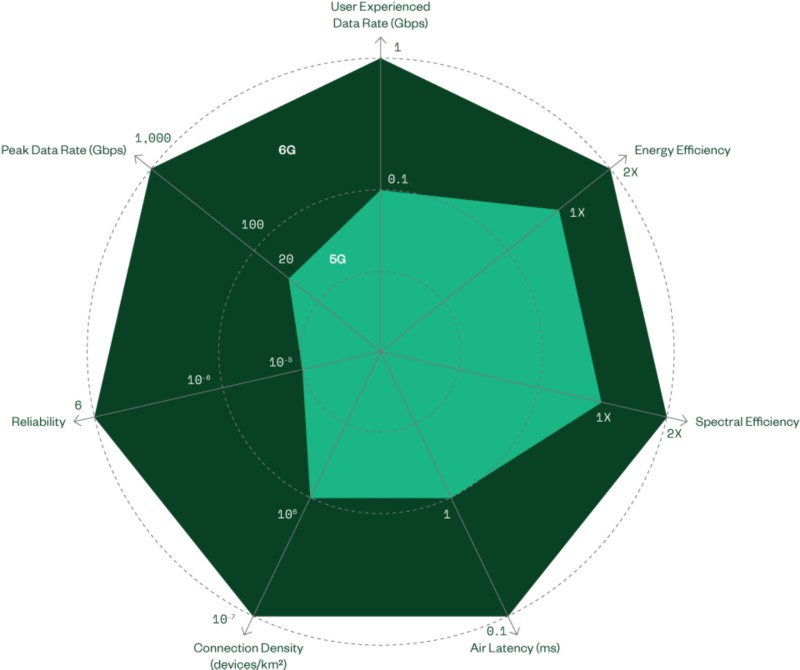
Figure 2: 5G to 6G Areas of Improvement.
Image reference courtesy of the Advanced Communications Research Center at Samsung Research
These applications will change the way we communicate and interact in an increasingly connected world. Of course, these applications are enabled only through specific technologies capable of handling the technically challenging demands. This requires enhancing and optimizing existing techniques, developing novel implementations, and perhaps most importantly, methods to test and quickly develop devices that will make them a reality.
Continued Enhancement of 5G Technologies
Before diving into the specifics of 5G Advanced and the associated changes, it is worth mentioning this is a very PHY/RF-centric view. On higher layers, a few other innovations have taken place, including network slicing, foundations for RAN disaggregation, of which O-RAN is a part, support of non-public networks (like campus networks), and much better QoS capabilities compared to LTE to serve eMBB, URLLC, and mMTC needs. While these are crucial in the implementation and deployment of future wireless networks, this white paper will focus on PHY layer improvements and some of the related test implications.
The introduction of 5G brought along many useful technologies to increase data rates, spectral efficiency, and lower latency to achieve never-before-seen performance; 5G Advanced will continue this trend and continue development from previous releases.
Low Bandwidth UEs
Among the areas of improvement for Release 18 are reduced power consumption and specifications for UEs using bandwidths of 5, 10, and 20 MHz. These requirements introduce new challenges in the development of these devices, known as reduced capacity (REDCap) devices. With lower power consumption comes lower power measurements—with dynamic range, noise floor, and absolute accuracy becoming a much higher concern in how these measurements are taken. Key performance indicators, consumption models, and evaluation methodologies will need to be well defined with set test criteria.
One example of new tests to be conducted include a BS to UE “wake-up” signals or enabling gNB “sleep mode.” In both cases, allowing components to shut off, and thus not consume power when they are not needed, can greatly increase efficiency of network devices. However, this can come with downsides if not implemented correctly. Quick, efficient, and reliable “wake-up” signals with minimal delays will be crucial to ensure maximize reliability and network capacity and reduce latency when devices are continually turning on and off.
Power Consumption Reduction on the BS and UE Side (Green Networks)
Another factor in network efficiency is the efficiency of individual components. RF front ends need to be optimized to ensure the most efficient power consumption possible. 5G Advanced aims to reduce power consumption and increase network efficiency, which can come in the form of optimized digital predistortion (DPD) algorithms for improved linearity or envelope tracking to increase power amplifier (PA) efficiency. Both require a highly versatile and open system for quick characterization and visualization and easy implementation for a wider range of test cases, as well as the ability to test bandwidths from 5 MHz to 400 MHz. Inefficiencies when transitioning test cases—or long setup times—will likely mean significantly longer validation timelines, impacting time to market.
DPD can be challenging to implement with many choices of DPD algorithms that become increasingly complex, especially as PA designs also become more complex. Many DPD algorithms can no longer keep up with the more dynamically changing PA behavior at different frequency and power levels, for example. Additionally, DPD often requires three to five times the signal bandwidth for proper implementation. This can mean anywhere from 1600 to 2000 MHz bandwidth for some of the latest 5G NR waveforms.
NI has considered a variety of these challenges in PA validation and has worked to address them with solutions that allow for extensive DPD customizability, all while still being easy to implement and analyze.
Learn more about RFFE Validation for evaluating PAs under DPD conditions
Methodology Changes for FR2 Frequencies
There have been a few noticeable changes for mmWave (FR2) specifications and test methodology. One of these changes is support for UL 256-QAM for FR2-1 (24.25–52.6 GHz). This is a modulation scheme that comes with tricky implementation at a higher frequency range. With the higher frequency, wider bandwidths, and thus higher noise floor, modulation accuracy becomes more difficult, especially when accounting for the higher path loss and lower accuracy at FR2 frequencies. Test equipment capable of reaching a low EVM measurement even at these higher frequencies will be necessary for successful implementation.
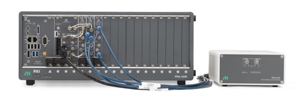
Figure 3: PXIe-5842 with 54 GHz Frequency Extension
With coverage up to 54 GHz, the PXIe-5842 with 54 GHz Frequency Extension includes full coverage of 5G FR2 frequencies and delivers best-in-class EVM performance for higher order modulation schemes.
Learn more about mmWave test with PXI VSTs
Adding to the changes for mmWave frequencies, one of the more obvious Release 18 developments that affects test engineers is the change of test methodologies for FR2. This is a continuation of developments in Release 15 through Release 17, with a few noticeable exceptions. First is the inclusion of up to four DL MIMOs on two panels. With multiple panels simultaneously active, even minimal power leakage into adjacent channels can cause a degraded signal, and true phase-coherent synchronization must be achieved to ensure coexistence. While this change to test methodologies for FR2—along with many of the other developments discussed up until now, are a continuation of previous 5G development—they all contain an intentional shift to new practices that are in the direction of 6G wireless networks, as we will now explore further.
“Beyond 5G” Technologies
As mentioned previously, 3GPP Release 18 is the first to hold the title of “5G Advanced.” This is due to the increased focus on the future of cellular communications: 6G. There are many improvements that will pave the way for this transition, some of which include advanced MIMO evolution, implementation of full duplex antenna arrays, and AI/ML on the air interface.
Figure 4: 5G Advanced Logo
Advanced MIMO Evolution
Until now, MIMO systems were not feasible at low frequencies due to large antenna form factor sizes. This is set to change with modular massive multiple input multiple output (mmMIMO). As the name implies, this is set to standardize the way base station antennas are deployed and reduce the footprint as much as possible by spatially distributing modular antenna components.
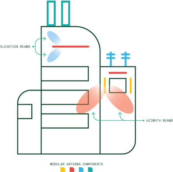
Figure 5: mmMIMO Deployment Diagram
This standardization of MIMO antenna arrays is set to lower cost and reduce development efforts for the base station components. Independent antenna modules resembling building blocks will reduce complexity in implementation by being modular; they can be combined in different ways to build an antenna array, making them more adaptable to the spatial constraints of a predefined area. Another way this will help reduce implementation limitations is through the physical distribution of arrays spatially, over a larger area. Figure 5 is an example of different, independent antenna modules operating cohesively on a predefined structure or building.
While this will significantly reduce spatial limitations by spreading out large elements, there are a few challenges facing its implementation. Distributed antenna arrays will require ultra-low latency connections, necessitating better timing and synchronization from base station components that are physically farther apart. Distributed antennas also need better calibration for reliable connections, and implementation on the disaggregated RAN architecture introduces new test cases based on standardized interfaces between base station components. More complexity in implementation means more complexity in test, with each subsystem connection requiring some level of integration and full in-the-loop system level tests (which can be difficult to set up) becoming increasingly common.
NI and partners together realize the challenges in test of increasingly complex base station components, both in the traditional RAN and for Open RAN. NI has partnered with Spirent Communications for Open RAN O-RU validation, allowing for comprehensive validation of O-RUs with robust emulation capabilities. Leveraging the expertise of NI and its partners can help streamline complex wireless infrastructure test development.
Learn more about NI wireless infrastructure test solutions
Path Towards Full Duplex
Another development to enhance the speed and performance of 5G Advanced is the implementation of full duplex transmissions. Until recently, this was not feasible at high power and was only used in low-power applications such as WiFi. Known as sub-band full duplex (SBFD or XDD), this technology allows for simultaneous uplink and downlink using non-overlapping adjacent subchannels within the same TDD band for ultra-low latency and high-reliability connections.
This is done with self-interference cancellation (SIC) at the base station, which allows simultaneous transmission on a single channel, subchannels, a pair of partially overlapping channels, or any pair of channels in the same frequency band. This will allow for much more efficient spectrum use without compromising throughput; SBFD requires much less spectrum than traditional FDD, while maintaining continuous UL and DL transmissions and low latency that is not possible with TDD. For 5G Advanced, this development applies primarily to the base station side; no major changes are happening on the UE side.
SBFD, of course, will come with many technical challenges in implementation that would need to be addressed. Interference in the UL and DL directions is much higher during simultaneous transmission, with new suppression techniques needed (and tested) during development. This could include new circuitry or filtering in RF front ends, digital implementations such as DPD, or other forms of digital signal processing (DSP). Whatever the case, it is another set of test cases to be validated, documented, and analyzed for proper implementation.
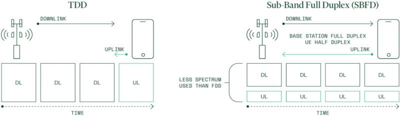
Figure 6: Sub-Band Full Duplex (SBFD) Diagram
SBFD is a crucial development since it is likely the first of many steps on the path towards single frequency full duplex (SFFD), or true full duplex, which will use the same frequency for two-way communication. Full duplex will present unique challenges in RF front-end development and will be a major topic of discussion, and technical challenge, for future 6G 3GPP releases.
Mobile mmWave Technology Evolution
A significant change is in the works for mobile mmWave technology. Integrated access backhaul (IAB) is set to expand capabilities on cars and trains for better coverage in sub-6 GHz and mmWave deployments. Additionally, optimized sidelink operations in unlicensed 5 GHz and 6 GHz bands, multibeam operations, and sidelink carrier aggregation will enable new levels of connectivity and reliability by further integrating devices on the network. Sidelink enhancements will include mechanisms to support device-to-device (UE-to-UE) relay, allowing users to receive information from networks via other users.
As opposed to the traditional single UL and DL connections, devices operating on 5G Advanced networks will interface with a web of connections, bringing about complexity in the way they communicate. With multiple simultaneous UL, DL, and sidelink connections, the way the information on each is split up in frequency, time, direction, and space will become an increasingly complex task for the RF front ends and digital signal processing (DSP) of tomorrow’s 5G devices.
FR3 Frequencies
mmWave has not yet gained the widespread adoption that was predicted just a few years ago. While it certainly has its use cases and has seen growth in some niche applications such as ultra-dense, high-traffic applications (stadiums or city centers, for example), widespread implementation has proved technically challenging and costly. Due to its shorter range, many small cells are required, and existing network infrastructure cannot be reused for mmWave frequencies.
Despite the slow growth of 5G mmWave, there is another potential range of spectrum that can potentially merge the best of both worlds. There is another option that combines mmWave’s benefits (high throughput and relatively open spectrum) with the ease of implementation and larger area coverage that are benefits of sub‑6 GHz cellular networks.
This “sweet spot” in the wireless spectrum is known as FR3. It consists of frequencies from 7.125 GHz to 24.25 GHz and acts as a compromise in cellular communications, balancing both the pros and cons of sub‑6 GHz and mmWave frequencies.
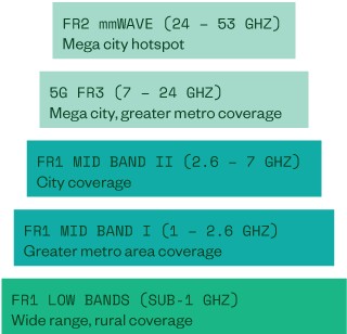
Figure 7: Cellular Frequency Bands
While test at FR3 frequencies is, technically speaking, not as challenging as those at mmWave, RF front ends for UEs and infrastructure will not operate on these frequencies exclusively. The mixed use of sub‑6 GHz , FR3, and mmWave frequencies will exist, often on the same RF front ends and systems. This will no doubt introduce an increase in test cases, both for each distinct frequency range, and with interoperability and coexistence of multiple frequency ranges simultaneously.
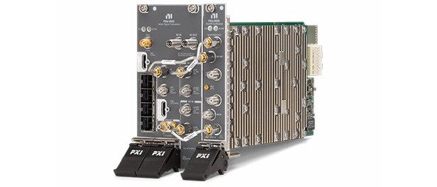
Figure 8: PXIe-5842 Vector Signal Transceiver
With continuous frequency coverage up to 26.5 GHz, the PXIe-5842 is well suited to address test requirements at both sub 6 GHz and FR3 frequencies and is a central instrument in a consolidated and future-proof test system.
Learn more about PXI Vector Signal Transceivers
AI-Enabled Air Interface
The last major development in 5G Advanced—and the one that arguably will have the most significant impact in the long term—is AI/ML for NR-enabled air interface. While the implications of these proposed changes remain to be seen, it certainly has been a popular topic that has gained vast interest from many key players in the industry. AI/ML could very well change the way systems are tested from a parametric test methodology towards a more scenario-based test methodology.
An AI-enabled cellular network can become much more efficient, automating tasks that previously required human intervention. To enable this, a large amount of data collected from network infrastructure has the potential to allow these smart networks to solve complex problems and implement solutions as required in a much more versatile system.
5G Non-Terrestrial Networks (NTNs)
A 5G NTN is a form of satellite communications designed for 5G that involves the use of satellites for IoT and broadband connectivity. While use cases are still to be determined, potential uses in UEs, connected vehicles, and fixed and broadcast satellite services makes it an intriguing area of development. Even today, many UEs are designed with some form of NTN capabilities—setting the stage for truly global communications, even in the most remote or rural locations, far from existing cellular infrastructure.
While this capability could transform how we communicate globally, NTN will need to account for some inherent technical challenges. The nature of satellite communication introduces high latency, Doppler shift, and path loss. This is because of the long distances that the UE is from the satellite, the high-speed relative to a stationary object, and the effects of elevation, beam footprint, and atmospheric interference on transmitted signals. Additionally, some of the potential frequencies proposed for NTN communication ranges from just a few MHz in the L band up to the Ka or Ku band with bandwidths up to 5 GHz, which presents wide-ranging behaviors from different waveforms.
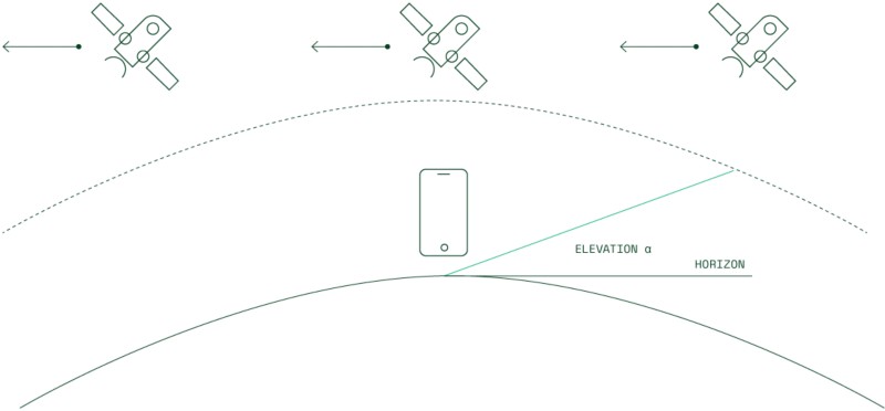
Figure 9: Varying Amounts of Doppler Shift at Different Satellite Locations
Implications for RF Test Engineers
There have been many topics discussed that each have their own implications for engineers responsible for design, validation, and production of 5G Advanced devices. While many situational considerations have been discussed, a few generalizations will be touched on that transcend most 5G Advanced developments.
One of these is the vast increase in test cases that will result as a side effect of the developments in 5G Advanced. Each new 5G Advanced device brings about many configurable parameters, each of which need to be validated by many different test cases. From more modulation types to multiple antenna arrays at different frequencies and simultaneous UL and DL connections, as well as sidelink UE-to-UE transmissions and power efficiency considerations, there are simply more scenarios that need to be validated for 5G Advanced. This will substantially increase the number of test cases, meaning an efficient means of cycling through device validation will be key to ensure fast time to market while maintaining meaningful insights from the data collected.
Another example is the constant specification updates required to enable these developments, which can be difficult to track to ensure new test cases and measurements are incorporated and specifications met. With quarterly releases and standard specific personalities such as RFmx NR, RFmx can be a useful tool for standards-based measurements.
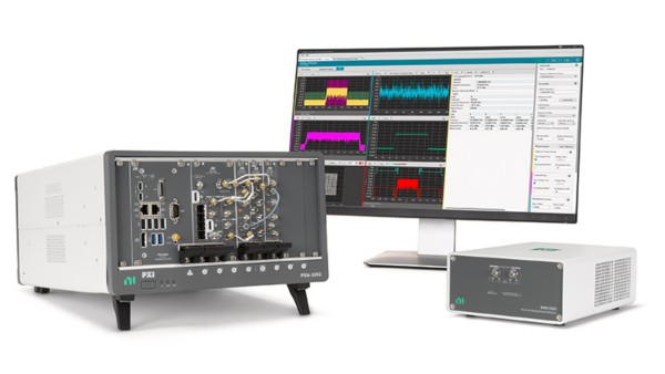
Figure 10: Complete Hardware and Software Solutions for Wireless Test Applications
The list goes on, with many unique and novel test requirements set to appear as cellular technology continues to develop. NI aims to be a partner in these endeavors, providing the tools, workflows, and systems needed to develop the next and future generations of wireless communications. Contact NI and speak to a technical expert for more information on how NI can help you prepare for the future of wireless communications.
Neither Emerson, Emerson Automation Solutions, nor any of their affiliated entities assumes responsibility for the selection, use, or maintenance of any product. Responsibility for proper selection, use, and maintenance of any product remains solely with the purchaser and end user.
National Instruments, NI, and NI.com are marks owned by one of the companies in the Test & Measurement business unit of Emerson Electric Co. Emerson and the Emerson logo are trademarks and service marks of Emerson Electric Co. An NI Partner is a business entity independent from NI and has no agency or joint-venture relationship and does not form part of any business associations with NI.
The contents of this publication are presented for informational purposes only, and while every effort has been made to ensure their accuracy, they are not to be construed as warranties or guarantees, express or implied, regarding the products or services described herein or their use or applicability. All sales are governed by our terms and conditions, which are available upon request. We reserve the right to modify or improve the designs or specifications of such products at any time without notice.
NI
11500 N Mopac Expwy
Austin, TX 78759-3504
© 2024 National Instruments. All rights reserved.