Hardware-in-the-Loop (HIL) Test System Architectures
Overview
You can test embedded control systems more efficiently with the powerful method of hardware-in-the-loop (HIL) simulation. Safety, availability, or cost considerations can make it impractical to perform all the necessary tests with the complete embedded control system. Using HIL simulation, you can simulate the parts of the system that pose these challenges. By thoroughly testing the embedded control device in a virtual environment before proceeding to real-world tests of the complete system, you can maintain reliability and time-to-market requirements in a cost-effective manner even as the systems you are testing become more complex.
Contents
- Components of an HIL Test System
- Hardware Fault Insertion
- Testing Multi-ECU Systems
- Additional Processing Power – Distributed Processing
- Simplified Wiring – Distributed I/O
- Implementing HIL Test Systems
- Next Steps
Components of an HIL Test System
An HIL test system consists of three primary components: a real-time processor, I/O interfaces, and an operator interface. The real-time processor is the core of the HIL test system. It provides deterministic execution of most of the HIL test system components such as hardware I/O communication, data logging, stimulus generation, and model execution. A real-time system is typically necessary to provide an accurate simulation of the parts of the system that are not physically present as part of the test. The I/O interfaces are analog, digital, and bus signals that interact with the unit under test. You can use them to produce stimulus signals, acquire data for logging and analysis, and provide the sensor/actuator interactions between the electronic control unit (ECU) being tested and the virtual environment being simulated by the model. The operator interface communicates with the real-time processor to provide test commands and visualization. Often, this component also provides configuration management, test automation, analysis, and reporting tasks.
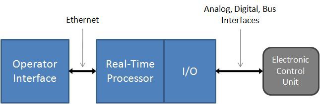
Figure 1. An HIL test system consists of three primary components: an operator interface, a real-time processor, and I/O interfaces.
Hardware Fault Insertion
Many HIL test systems use hardware fault insertion to create signal faults between the ECU and the rest of the system to test, characterize, or validate the behavior of the device under these conditions. To accomplish this, you can insert fault insertion units (FIUs) between the I/O interfaces and the ECU to allow the HIL test system to switch the interface signals between normal operation and fault conditions such as a short-to-ground or open circuit.
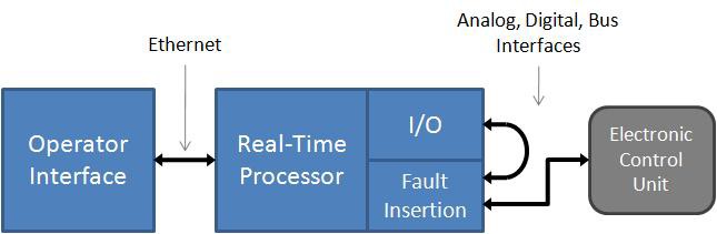
Figure 2. You can use hardware fault insertion to test the behavior of the ECU during signal faults.
Testing Multi-ECU Systems
Some embedded control systems, such as an automobile, aircraft, or wind farm, use multiple ECUs that are often networked together to function cohesively. Although each of these ECUs may initially be tested independently, a system’s integration HIL test system, such as a full vehicle simulator or iron bird simulator, is often used to provide more complete virtual testing.
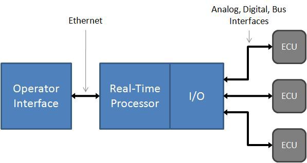
Figure 3. Automobiles, aircraft, and wind farms use multiple ECUs.
When testing a multi-ECU control system (and even some single ECU control systems), two needs often arise: additional processing power and simplified wiring.
Additional Processing Power – Distributed Processing
Even with the latest multicore processing power, some systems require more processing power than what is available in a single chassis. To address this challenge, you can use distributed processing techniques to meet the performance requirements of these systems. In very high-channel-count systems, the need is more than simply additional processing power, additional I/O is also necessary. In contrast, systems using large, processor-hungry models often use additional chassis only for the extra processing power, allowing those processors to remain dedicated to a single task for greater efficiency. Depending on how the simulator tasks are distributed, it may be necessary to provide shared trigger and timing signals between the chassis as well as deterministic data mirroring to allow them to operate cohesively.
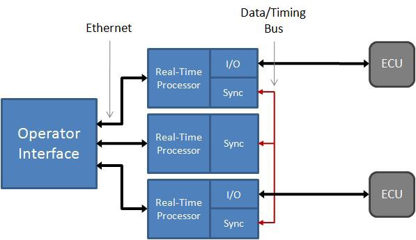
Figure 4. When using multiple chassis for additional processing power, it is often necessary to provide timing and data synchronization interfaces between them.
Simplified Wiring – Distributed I/O
Implementing and maintaining wiring for high-channel-count systems can pose costly and time-consuming challenges. These systems can require hundreds to thousands of signals be connected between the ECU and the HIL test system, often spanning many meters to compensate for space requirements.
Fortunately, deterministic distributed I/O technologies can help you tame these wiring complexities and provide modular connectivity to ECUs, which allows for efficient system configuration modifications. Instead of routing all connections back to a single rack containing one or more real-time processing chassis instrumented with I/O interfaces, you can use deterministic distributed I/O to provide modular I/O interfaces located in close proximity to each ECU without sacrificing the high-speed determinism necessary for accurate simulation of the virtual parts of the system.
This approach greatly reduces HIL test system wiring cost and complexity by making it possible for the connections between the ECU and the I/O interfaces to be made locally (spanning less than a meter) while a single bus cable is used to span the additional distance to the real-time processing chassis. Additionally, with the modular nature of this approach, HIL test systems can easily scale, incrementally, from a multi-ECU test system in which all but one of the ECUs are simulated to a complete systems integration HIL test system where none of the ECUs are simulated.
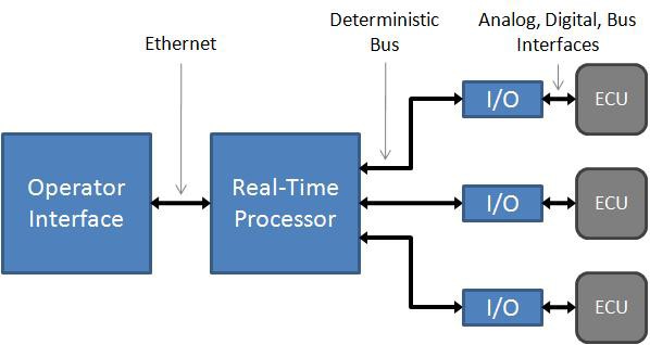
Figure 5. Deterministic distributed I/O interfaces greatly reduce HIL test system wiring cost and complexity because the connections between the ECU and the I/O interfaces can be made locally.
Implementing HIL Test Systems
Once you have selected the appropriate architecture for your HIL test system, the first step in creating a HIL test system is to select the components that best meets your development requirements. National Instruments provides a wide variety of real-time processing and I/O options for implementing HIL test systems. Because they are all based on open industry standards, you can be assured that they always deliver the latest advances in PC technology to your HIL test system and always meet future test system requirements.
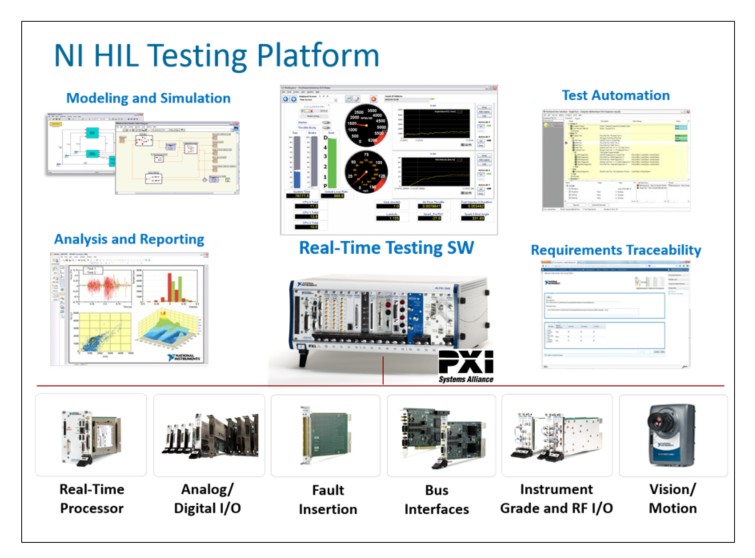
The National Instruments HIL platform is open and extensible, which means that it can adapt to changing system requirements. Because its modular architecture, the NI HIL platform can be easily upgraded with additional functionality, which helps you future proof your test systems and meet the requirements of the most demanding embedded software testing applications. In addition to the widest range of I/O on market, National Instruments offers software tools that enable to automate your HIL tests, perform post processing and report generation, and map test results to requirements. These tools help you perform a wider range of tests earlier in the software development process, which reduces overall development cost while improving product quality.