Controller Area Network (CAN) Overview
Contents
- What is CAN?
- CAN History
- CAN Benefits
- CAN Applications & Examples
- CAN Physical Layers
- CAN Protocol Terminology
- CAN Database Files
- How CAN Communication Works
- National Instruments CAN Tools
What is CAN?
A controller area network (CAN) bus is a high-integrity serial bus system for networking intelligent devices. CAN busses and devices are common components in automotive and industrial systems. Using a CAN interface device, you can write LabVIEW applications to communicate with a CAN network.
CAN History
Bosch originally developed CAN in 1985 for in-vehicle networks. In the past, automotive manufacturers connected electronic devices in vehicles using point-to-point wiring systems. Manufacturers began using more and more electronics in vehicles, which resulted in bulky wire harnesses that were heavy and expensive. They then replaced dedicated wiring with in-vehicle networks, which reduced wiring cost, complexity, and weight. CAN, a high-integrity serial bus system for networking intelligent devices, emerged as the standard in-vehicle network. The automotive industry quickly adopted CAN and, in 1993, it became the international standard known as ISO 11898. Since 1994, several higher-level protocols have been standardized on CAN, such as CANopen and DeviceNet. Other markets have widely adopted these additional protocols, which are now standards for industrial communications. This white paper focuses on CAN as an in-vehicle network.
CAN Benefits
Low-Cost, Lightweight Network
CAN provides an inexpensive, durable network that helps multiple CAN devices communicate with one another. An advantage to this is that electronic control units (ECUs) can have a single CAN interface rather than analog and digital inputs to every device in the system. This decreases overall cost and weight in automobiles.
Broadcast Communication
Each of the devices on the network has a CAN controller chip and is therefore intelligent. All devices on the network see all transmitted messages. Each device can decide if a message is relevant or if it should be filtered. This structure allows modifications to CAN networks with minimal impact. Additional non-transmitting nodes can be added without modification to the network.
Priority
Every message has a priority, so if two nodes try to send messages simultaneously, the one with the higher priority gets transmitted and the one with the lower priority gets postponed. This arbitration is non-destructive and results in non-interrupted transmission of the highest priority message. This also allows networks to meet deterministic timing constraints.
Error Capabilities
The CAN specification includes a Cyclic Redundancy Code (CRC) to perform error checking on each frame's contents. Frames with errors are disregarded by all nodes, and an error frame can be transmitted to signal the error to the network. Global and local errors are differentiated by the controller, and if too many errors are detected, individual nodes can stop transmitting errors or disconnect itself from the network completely.
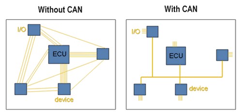
Figure 1. CAN networks significantly reduce wiring.
CAN Applications & Examples
CAN was first created for automotive use, so its most common application is in-vehicle electronic networking. However, as other industries have realized the dependability and advantages of CAN over the past 20 years, they have adopted the bus for a wide variety of applications. Railway applications such as streetcars, trams, undergrounds, light railways, and long-distance trains incorporate CAN. You can find examples of CAN devices linking the door units, brake controllers, passenger counting units, and more on different levels of the multiple networks within these vehicles. CAN also has applications in aircraft with flight-state sensors, navigation systems, and research PCs in the cockpit. In addition, you can find CAN buses in many aerospace applications, ranging from in-flight data analysis to aircraft engine control systems such as fuel systems, pumps, and linear actuators.
Medical equipment manufacturers use CAN as an embedded network in medical devices. In fact, some hospitals use CAN to manage complete operating rooms. Hospitals control operating room components such as lights, tables, cameras, X-ray machines, and patient beds with CAN-based systems. Lifts and escalators use embedded CAN networks, and hospitals use the CANopen protocol to link lift devices, such as panels, controllers, doors, and light barriers, to each other and control them. CANopen also is used in nonindustrial applications such as laboratory equipment, sports cameras, telescopes, automatic doors, and even coffee machines.
CAN Physical Layers
CAN has several different physical layers you can use. These physical layers classify certain aspects of the CAN network, such as electrical levels, signaling schemes, cable impedance, maximum baud rates, and more. The most common and widely used physical layers are described below:
High-Speed/FD CAN
High-speed CAN is by far the most common physical layer. High-speed CAN networks are implemented with two wires and allow communication at transfer rates up to 1 Mbit/s. Other names for high-speed CAN include CAN C and ISO 11898-2. Typical high-speed CAN devices include antilock brake systems, engine control modules, and emissions systems. CAN with Flexible Data-Rate (CAN FD) is the next generation of high-speed CAN communication with evolving standards for higher data rates. NI has enabled speeds up to 8 Mbit/s using the TJA1041 and TJA1043 transceivers through the NI-XNET driver. As transceiver vendors complete qualifications for CAN FD speeds, NI will update our documentation as necessary.
Low-Speed/Fault-Tolerant CAN Hardware
Low-speed/fault-tolerant CAN networks are also implemented with two wires, can communicate with devices at rates up to 125 kbit/s, and offer transceivers with fault-tolerant capabilities. Other names for low-speed/fault-tolerant CAN include CAN B and ISO 11898-3. Typical low-speed/fault-tolerant devices in an automobile include comfort devices. Wires that have to pass through the door of a vehicle are low-speed/fault-tolerant in light of the stress that is inherent to opening and closing a door. Also, in situations where an advanced level of security is desired, such as with brake lights, low-speed/fault-tolerant CAN offers a solution.
Single-Wire CAN Hardware
Single-wire CAN interfaces can communicate with devices at rates up to 33.3 kbit/s (88.3 kbit/s in high-speed mode). Other names for single-wire CAN include SAE-J2411, CAN A, and GMLAN. Typical single-wire devices within an automobile do not require high performance. Common applications include comfort devices such as seat and mirror adjusters.
Software-Selectable CAN Hardware
With National Instruments CAN hardware products, you can configure the software-selectable CAN interfaces to use any of the onboard transceivers (high-speed, low-speed/fault-tolerant, or single-wire CAN). Multiple-transceiver hardware offers the perfect solution for applications that require a combination of communications standards. With software-selectable CAN hardware, you also can choose your own external CAN transceiver.
CAN Programming in LabVIEW and Other Languages
NI-XNET Software Driver
NI-XNET software is included with PCI/PXI-851x and NI 986x devices and is available as a free download on ni.com. This new driver is used to develop CAN, local interconnect network (LIN), and FlexRay applications in NI LabVIEW, NI LabWindows/CVI, and C/C++ on Windows and LabVIEW Real-Time OSs. As part of the NI-XNET platform, NI 851x and NI 986x devices work well for applications requiring real-time, high-speed manipulation of hundreds of frames and signals, such as hardware-in-the-loop simulation, rapid control prototyping, bus monitoring, automation control, and more.
NI-XNET: One API, Many Embedded Networks
The NI-XNET platform combines a series of high-performance CAN, LIN, and FlexRay interfaces with the NI-XNET API, a common set of easy-to-use functions for reading and writing CAN, LIN, and FlexRay frames and signals.
Top Performance With Less Programming
NI-XNET interfaces bring together the performance associated with low-level microcontroller programming and the speed and power of Windows and LabVIEW Real-Time OS development. The patent-pending NI-XNET device-driven DMA engine reduces system latency, a common pain point for PC-based CAN interfaces, from milliseconds to microseconds. The engine enables the onboard processor to move CAN frames and signals between the interface and the user program without CPU interrupts, freeing host processor time for processing complex models and applications.
For more information about the benefits and applications of NI-XNET, refer to the NI-XNET CAN, LIN, and FlexRay Platform Overview.
NI-CAN Software Driver
National Instruments includes NI-CAN driver software with all National Instruments Legacy CAN interfaces and provides it as a free software download on ni.com. With other CAN interfaces, you can take advantage of only a small percentage of the board functionality if you do not purchase the turnkey software tool. However, all of the National Instruments CAN board functionality is fully exposed, so you can develop your own custom-defined applications in the programming language of your choice. The NI-CAN driver provides high-level, easy-to-use functions to help you develop entire CAN applications quickly, saving you both time and money.
There are two APIs exposed with the NI-CAN driver software. The Frame API is the original API for CAN programming. In the Frame API, you can transmit and receive CAN frames that contain raw data bytes. Your program must parse and scale these bytes to come up with scaled engineering units. For more information on programming with the Frame API, view the "Using the Frame API" section of the NI CAN Hardware and Software Manual.
NI first introduced the Channel API in the NI-CAN 2.0 driver software. You can read from and write to CAN channels using channel names defined in database files (.dbc or .ncd). The Channel API provides the following benefits:
- High-level programming
- Easy-to-use physical units
- Primary use for easy CAN/data acquisition synchronization
- Ability to incorporate Vector database files
For more information about programming with the Channel API, refer to NI-CAN Channel API documentation.
CAN Protocol Terminology
CAN devices send data across the CAN network in packets called frames. A CAN frame consists of the following sections.
- CAN Frame -- an entire CAN transmission: arbitration ID, data bytes, acknowledge bit, and so on. Frames also are referred to as messages.
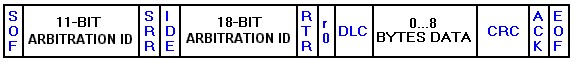
Figure 2. The standard CAN frame format.
- SOF (start-of-frame) bit – indicates the beginning of a message with a dominant (logic 0) bit.
- Arbitration ID – identifies the message and indicates the message's priority. Frames come in two formats -- standard, which uses an 11-bit arbitration ID, and extended, which uses a 29-bit arbitration ID.
- IDE (identifier extension) bit – allows differentiation between standard and extended frames.
- RTR (remote transmission request) bit – serves to differentiate a remote frame from a data frame. A dominant (logic 0) RTR bit indicates a data frame. A recessive (logic 1) RTR bit indicates a remote frame.
- DLC (data length code) – indicates the number of bytes the data field contains.
- Data Field – contains 0 to 8 bytes of data.
- CRC (cyclic redundancy check) – contains 15-bit cyclic redundancy check code and a recessive delimiter bit. The CRC field is used for error detection.
- ACK (ACKnowledgement) slot – any CAN controller that correctly receives the message sends an ACK bit at the end of the message. The transmitting node checks for the presence of the ACK bit on the bus and reattempts transmission if no acknowledge is detected. National Instruments Series 2 CAN interfaces have the capability of listen-only mode. Herein, the transmission of an ACK bit by the monitoring hardware is suppressed to prevent it from affecting the behavior of the bus.
- CAN Signal – an individual piece of data contained within the CAN frame data field. You also can refer to CAN signals as channels. Because the data field can contain up to 8 bytes of data, a single CAN frame can contain 0 to 64 individual signals (for 64 channels, they would all be binary).
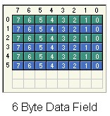
Figure 3. Signals can be defined as a certain number of bits inside of a CAN frame.
CAN Database Files
CAN database files are text files that contain scaling information for CAN frames and signal definitions. National Instruments NI-XNET database editor software recognizes FIBEX database files (.xml), Vector database files (*.dbc), and National Instruments CAN database files (*.ncd).
For each signal, CAN databases define rules for conversion to engineering units. The following data is stored in databases:
- Channel name
- Location (start bit) and size (number of bits) of the channel within a given message
- Byte order (Intel/Motorola)
- Data type (signed, unsigned, and IEEE float)
- Scaling and units string
- Range
- Default value
- Comment
You can use this information to easily convert the "raw" frame information (usually bytes) to a "real world" value. The picture below illustrates an example of this conversion.
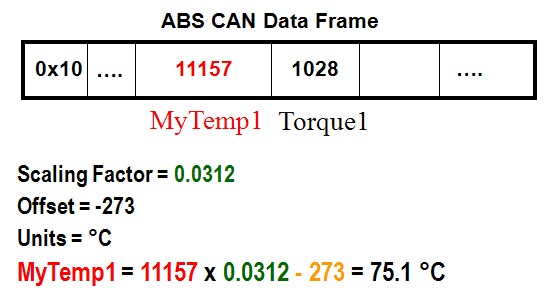
Figure 4. All of the necessary scaling data is contained in a database for converting frames to signals.
CAN database files may contain frame and signal definitions for an entire vehicle. Every network has its own unique database file. Additionally, these database files are vendor-specific and usually confidential.
By using a database file for many frames on the CAN network, many CAN APIs (like NI-XNET) can automatically convert the frame information directly to a real-world value. This simplifies application development because you never need to worry about the raw frame values.
How CAN Communication Works
As stated earlier, CAN is a peer-to-peer network. This means that there is no master that controls when individual nodes have access to read and write data on the CAN bus. When a CAN node is ready to transmit data, it checks to see if the bus is busy and then simply writes a CAN frame onto the network. The CAN frames that are transmitted do not contain addresses of either the transmitting node or any of the intended receiving node(s). Instead, an arbitration ID that is unique throughout the network labels the frame. All nodes on the CAN network receive the CAN frame, and, depending on the arbitration ID of that transmitted frame, each CAN node on the network decides whether to accept the frame.
If multiple nodes try to transmit a message onto the CAN bus at the same time, the node with the highest priority (lowest arbitration ID) automatically gets bus access. Lower-priority nodes must wait until the bus becomes available before trying to transmit again. In this way, you can implement CAN networks to ensure deterministic communication among CAN nodes.
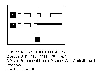
Figure 5. CAN contains built in priority for messages to avoid conflicts.
National Instruments CAN Tools
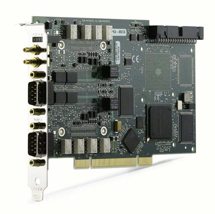
NI provides a variety of hardware and software tools for CAN application development. NI offers CAN interfaces for different platforms including PCI, PXI, USB, CompactRIO, and CompactDAQ (C Series). For PCI, PXI, and C Series, you can choose from high-speed/FD, low-speed/fault-tolerant, and single-wire physical layers. For PCI and PXI, National Instruments provides the industry's first software-selectable CAN interface that contains a high-speed/FD, low-speed/fault-tolerant, and single-wire transceiver on each board, for each port, on a single device. This means you can simply select in your software which mode you want to use.
In addition, NI ships each of these devices with the appropriate driver software. NI CAN interface driver software is described below.
The National Instruments ECU Measurement and Calibration Toolkit extends the NI LabVIEW, NI LabWindows™/CVI, and C/C++ development environments to support measurement and calibration applications for the design and validation of electronic control units (ECUs). The ECU Measurement and Calibration Toolkit provides high-level, easy-to-use functions based on the CAN Calibration Protocol (CCP) that ECU designers, testers, and engineers can use to build their own customized measurement and calibration applications.
The mark LabWindows is used under a license from Microsoft Corporation. Windows is a registered trademark of Microsoft Corporation in the United States and other countries.