Spécifications expliquées : DAQ d’E/S NI multifonctions (MIO)
Aperçu
Contenu
- Introduction
- Comprendre la terminologie des spécifications
- Spécifications du sous-système analogique
- Spécifications du sous-système numérique
- Caractéristiques du compteur
- Autres caractéristiques
- Ressources supplémentaires
Introduction
Ce guide comprend les mêmes sections que la plupart des manuels de spécifications NI. Les termes et les définitions ci-dessous sont répertoriés par ordre alphabétique et peuvent apparaître dans un ordre différent dans les manuels de spécifications. Ce guide s’applique exclusivement aux périphériques et aux modules MIO DAQ des familles 60xx, 61xx, 62xx et 63xx (anciennement séries B, E, S, M et X). D’autres familles de produits NI telles que les châssis et contrôleurs cDAQ et cRIO, les modules des séries C 91xx, 92xx, 94xx, les RIO multifonctions série R 78xx, les multimètres numériques, les oscilloscopes/numériseurs et d’autres instruments peuvent utiliser une terminologie ou des méthodes différentes pour dériver les spécifications et par conséquent, ce guide ne doit pas être utilisé comme référence pour les périphériques et modules autres que ceux de la famille MIO DAQ.
À titre de référence, ce guide se fonde sur les périphériques NI 6361 et NI 6363. Si vous souhaitez suivre les spécifications de ces périphériques, vous pouvez le faire en suivant ce lien : Spécifications NI 6361 et NI 6363.
Comprendre la terminologie des spécifications
Tout d’abord, il est important de noter la différence catégorique entre les différentes spécifications. NI définit les capacités et les performances de ses instruments de test et de mesure comme des spécifications, des spécifications typiques et des caractéristiques ou des spécifications supplémentaires. Consultez le manuel de spécifications de vos périphériques pour plus de détails sur les spécifications garanties ou typiques.
- Les spécifications caractérisent les performances garanties de l’instrument dans l’intervalle d’étalonnage recommandé et dans les conditions de fonctionnement indiquées.
- Les spécifications typiques sont des spécifications respectées par la majorité des instruments dans l’intervalle d’étalonnage recommandé et dans les conditions de fonctionnement indiquées. Les spécifications typiques ne sont pas garanties.
- Les spécifications caractéristiques ou supplémentaires décrivent les fonctions et les attributs de base de l’instrument établis par conception ou pendant le développement et non évalués pendant la vérification ou l’ajustement. Elles fournissent des informations pertinentes pour l’utilisation adéquate de l’instrument qui ne figurent pas dans les définitions précédentes.
Spécifications du sous-système analogique
Les périphériques et les modules NI MIO DAQ peuvent avoir une entrée analogique, une sortie analogique ou une combinaison des deux systèmes. Il existe des spécifications propres à chaque sous-système, mais aussi certaines spécifications qui s’appliquent aux deux. Cette section est organisée en trois sections pour couvrir les spécifications communes, spécifiques à l’entrée analogique et spécifiques à la sortie analogique.
Entrée analogique et sortie analogique
Précision absolue à pleine échelle
La précision fait référence à la proximité de la valeur correcte d’une mesure. La précision absolue à pleine échelle est une précision théorique calculée en supposant que la valeur mesurée est la tension maximale prise en charge dans une plage donnée. La précision d’une mesure varie en fonction de l’évolution de la mesure, afin de pouvoir faire une comparaison entre les périphériques, la précision à pleine échelle est utilisée. Veuillez noter que la précision absolue à pleine échelle formule des hypothèses sur les variables d’environnement, telles qu’une température de fonctionnement à 25 °C, qui peuvent être différentes dans la pratique.
- Plage nominale positive à pleine échelle : la valeur positive maximale idéale qui peut être mesurée dans une plage particulière
- Plage nominale négative à pleine échelle : la valeur négative maximale idéale qui peut être mesurée dans une plage particulière
- Erreur de gain résiduel : erreur de gain inhérente à l’amplificateur d’instrumentation et connue pour exister après un auto-étalonnage
- Coefficient de température (Tempco) de gain : le coefficient de température qui décrit comment la température affecte le gain de l’amplificateur par rapport à la température lors du dernier auto-étalonnage
- Erreur d’offset résiduel : erreur d’offset inhérente à l’amplificateur d’instrumentation et connue pour exister après un auto-étalonnage
- Tempco de référence : le coefficient de température qui décrit la précision d’une mesure à une température spécifique par rapport à la température lors du dernier étalonnage externe
- Erreur INL (résolution de précision relative) : écart maximal entre la sortie de tension d’un C A/N et la sortie idéale ; erreur pouvant être considérée comme le pire cas de non-linéarité différentielle (DNL). Voir aussi : DNL
- Tempo d’offset : le coefficient de température qui décrit comment la température affecte l’offset dans une conversion C A/N par rapport à la température lors du dernier auto-étalonnage
- Bruit aléatoire/système : bruit système supplémentaire généré par le frontal analogique, mesuré en mettant à la masse la voie d’entrée
Exemple
Le NI PXIe-6363 a une plage de ± 0,5 V. La précision absolue à pleine échelle est calculée en supposant que le signal mesuré est de 0,5 V. La précision absolue à pleine échelle pour la plage de ± 0,5 V est de 100 µV.
Voir aussi
Comment calculer la précision absolue ou la précision d’un système ?
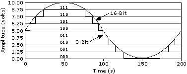
Résolution du convertisseur analogique/numérique (C A/N)
La résolution est le plus petit changement du signal en entrée que le périphérique ou le capteur peut détecter. Le nombre de bits utilisé pour représenter un signal analogique détermine la résolution du C A/N.
Exemple
Le NI PXIe-6363 est un périphérique 16 bits, ce qui signifie que le changement d’amplitude le plus faible détectable sur la plage ± 5 V est de 0,152 mV. Sur la plage ± 0,1 V, cette valeur est de 3,05 µV.
Rapport de réjection du mode commun (CMRR)
Lorsque le même signal est vu sur les entrées positives et négatives d’un amplificateur, le CMRR spécifie la quantité de ce signal qui est rejetée de la sortie finale (généralement mesurée en dB). L’amplificateur idéal supprimera tout le signal en mode commun, mais une telle situation est impossible dans l’implémentation.
Exemple
Le NI PXIe-6363 a une CMRR de 100 dB. Cela signifie qu’il atténuera les tensions de mode commun de 100 000x. Si le signal mesuré est un signal sinusoïdal pk de 5 V et que la tension d’offset ou commune entre les entrées positive et négative est de 5 VCC, la sortie finale rejettera ou atténuera l’entrée de 5 VCC à 5 µV. Le CMRR n’est pas inclus dans les dérivations de précision et doit être pris en compte séparément si le signal mesuré contient des tensions de mode commun.
Convertir l’intervalle
Le temps de stabilisation requis entre les voies dans une mesure multivoie.
Exemple
Le PCI-6221 a un intervalle de conversion allant de 4 à 7 µs, selon le niveau de précision requis par l’utilisateur.
Voir aussi
Couplage
Propriété de l’interface de deux circuits qui définit quels types de signaux sont transmis d’un côté à l’autre de l’interface. Il y a généralement deux options :
- Couplage DC : passera les signaux CA et CC
- Couplage CA : ne transmettra que les signaux CA, ce qui entraînera une implémentation matérielle de la suppression de l’offset CC d’un signal
Certains périphériques disposent d’un couplage sélectionnable par logiciel, tandis que d’autres sont dotés de CA ou CC.
Exemple
Le NI PXIe-6363 possède un couplage CC sur l’entrée analogique et la sortie analogique. Il ne prend pas non plus en charge le couplage CA.
Voir aussi
Interférence
La mesure de la quantité d’un signal sur une voie peut être couplée ou affectée sur une voie adjacente. L’interférence existe chaque fois qu’un signal variant en amplitude est présent sur un fil ou une trace de PCB qui est physiquement proche d’un autre fil ou trace de PCB.
Exemple
Le NI PXIe-6363 a une spécification d’interférences de -75 dB pour les voies adjacentes et de -95 dB pour les voies non adjacentes. Cela signifie que la voie ai2 aura une spécification d’interférence de -75 dB entre les voies ai1 et ai3, et une spécification d’interférence de -95 dB pour toutes les autres voies ai.
Mécanismes de transfert de données
Les périphériques NI transfèrent de façon bidirectionnelle les données du périphérique vers l’ordinateur (dans le cas d’une entrée) et de l’ordinateur vers le périphérique (dans le cas d’une sortie). Différents mécanismes de transfert de données sont utilisés en fonction du bus (USB, PXI Express, etc.). Certains bus peuvent prendre en charge plusieurs mécanismes de transfert. Reportez-vous à la documentation d’aide de NI-DAQmx pour plus d’informations sur des mécanismes spécifiques.
Exemple
L’USB-6341 prend en charge l’USB Bulk (Signal Stream) et les transferts de données d’E/S programmés. Le NI PXIe-6363 prend en charge l’accès direct à la mémoire (DMA) et les E/S programmées.
Voir aussi
Non-linéarité différentielle (DNL)
Différence entre la taille de pas idéale d’un C N/A (voir Résolution du convertisseur numérique/analogique [C N/A]) pour savoir comment calculer la taille de pas) et la valeur réelle qui est sortie (généralement mesurée en LSB). Dans un C N/A idéal, DNL serait 0 LSB.
Exemple
Le NI PXIe-6363 a un DNL de ± 1 LSB, ce qui signifie que pour toute valeur émise par C N/A, la valeur réelle peut être à ± 1 LSB de la valeur programmée. Par exemple, si l’utilisateur programme C N/A pour fournir une valeur de 1 V sur la plage ± 5 V, la sortie (sans les effets de précision) peut varier de :
L’INL est l’effet composé de DNL, la spécification INL est donc souvent utilisée dans les calculs de précision. Pour le NI PXIe-6363, la spécification INL dans le tableau de précision est de 64 ppm, ou 4 LSB, de la plage utilisée.
Résolution du convertisseur numérique/analogique (C N/A)
Le nombre de bits qui représente un signal analogique lors de la conversion à partir d’une valeur numérique.
Exemple
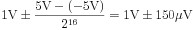
Le NI PXIe-6363 utilise des C N/A 16 bits, ce qui signifie qu’il existe 216 valeurs discrètes pouvant être sorties entre ± 5 V, ± 10 V ou une tension utilisateur fournie.
Voir aussi
Taille FIFO (analogique)
Les périphériques NI DAQ peuvent stocker des données dans un FIFO intégré lors de l’exécution de tâches d’entrée analogique ou de sortie analogique.
- Pour les tâches d’entrée, ce FIFO est utilisé pour buffériser les données avant que le driver logiciel NI-DAQmx transfère les données vers un emplacement pré-alloué dans la RAM appelé buffer PC.
- Pour les tâches de sortie, les données qu’un utilisateur demande à générer peuvent être bufférisées dans une combinaison du FIFO et du buffer PC.
Les périphériques dotés de voies d’entrée et de sortie auront un FIFO dédié pour chaque sous-système. Cependant, le FIFO est partagé sur toutes les voies au sein de ce FIFO. Pour l’entrée analogique, NI-DAQmx implémente des mécanismes de transfert de données pour garantir que les données stockées dans le FIFO sont transférées vers le buffer PC suffisamment rapidement pour que le FIFO intégré ne soit pas dépassé. Pour la sortie analogique, NI-DAQmx implémente des mécanismes de transfert de données pour garantir que les données du buffer PC sont transférées au FIFO intégré suffisamment rapidement pour que le FIFO ne soit pas sous-exploité. Pour la sortie analogique, il existe des propriétés sélectionnables par l’utilisateur pour spécifier s’il faut ou non utiliser le buffer PC, et pour régénérer un waveform unique à partir du FIFO intégré.
Exemple
Le NI PXIe-6363 a un FIFO d’entrée de 2 047 échantillons. Cela signifie qu’une tâche d’entrée avec quatre voies acquérant des données à un débit de 1 024 S/voie/s dépassera le FIFO embarqué en moins d’une demi-seconde :

NI-DAQmx utilise DMA pour transférer des données du FIFO vers la mémoire embarquée de l’ordinateur, connue sous le nom de buffer, pour éviter le dépassement.
Voir aussi
Configuration de la propriété de condition de requête de transfert de données dans NI-DAQmx
FIFO acquisition de waveforms (entrée numérique)
FIFO de génération de waveforms (sortie numérique)
Courant de polarisation d’entrée
Une conséquence d’avoir une impédance d’entrée finie est que le périphérique nécessite une petite quantité de courant pour pouvoir détecter un signal. Théoriquement, cette valeur devrait être de 0 A, mais en pratique ce n’est pas possible.
Exemple
Le NI PXIe-6363 a un courant de polarisation d’entrée de ± 100 pA. Cela signifie que tout capteur mesuré par le NI PXIe-6363 doit pouvoir fournir au moins autant de courant sur toute sa plage de sortie de tension afin d’être correctement numérisé.
Courant d’entrée pendant une condition de surtension
Lorsque le périphérique est en condition de surtension, il s’agit de la quantité de courant spécifiée que le périphérique va absorber.
Exemple
Le NI PXIe-6363 absorbe un maximum de ± 20 mA par broche dans un état de surtension. Dépasser cette valeur peut endommager les composants critiques.
Impédance d’entrée
L’impédance d’entrée est une mesure de la façon dont le circuit d’entrée empêche le courant de traverser vers la masse d’entrée analogique. Pour un C A/N idéal, cette valeur doit être infinie, ce qui signifie qu’aucun courant ne circulera de l’entrée à la masse, mais en pratique, ce n’est pas possible. L’implication d’une certaine impédance d’entrée finie est que le C A/N aura un certain degré de charge sur un circuit, en particulier ceux d’une impédance de sortie élevée. Il est typique que les capteurs aient une faible impédance de sortie.
Exemple
Le NI PXIe-6363 a une impédance d’entrée de Zin > 10 G Ω. En prenant le pire scénario d’impédance d’entrée la plus basse, vous pouvez visualiser une mesure asymétrique comme le circuit simplifié suivant, en supposant un capteur avec une impédance de sortie Zout = 150 Ω.
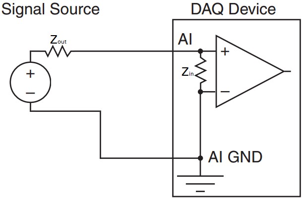
La combinaison en série de la sortie du capteur et de l’entrée du périphérique DAQ signifie que la tension sera divisée entre les deux valeurs d’impédance, l’impédance la plus grande supportant la majeure partie de la tension. Cela signifie que si la sensibilité de ce capteur est de 20 °C/V et mesure 100 °C (sortie 5 V), alors la tension mesurée par le dispositif DAQ sera la tension de sortie multipliée par le rapport de l’impédance d’entrée à la somme de l’impédance d’entrée DAQ et de sortie du capteur :
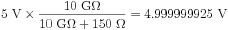
Cette différence de mesure de 75 nV correspond à une erreur de mesure de 5 °C presque négligeable due à l’impédance.
Pour illustrer un exemple où l’impédance d’entrée devient une spécification importante, prenons le cas hypothétique où un capteur a une impédance de sortie extrêmement élevée, telle que 5 GΩ. La connexion du périphérique DAQ à un capteur avec cette impédance de sortie extrêmement élevée provoque une sortie nominale de 5 V du capteur à 3,33 V, ou une erreur de mesure hypothétique de 33,4 °C.
Fréquence de mise à jour maximale
Pour la sortie analogique, la fréquence de mise à jour spécifie le nombre d’échantillons par seconde du C N/A en valeurs analogiques de tension ou de courant. La plupart des périphériques NI ont un C N/A unique par voie de sortie analogique, mais partagent tous le FIFO où les données de sortie analogique sont stockées. La vitesse à laquelle les données peuvent être lues à partir de ce FIFO et transférées vers les différents C N/A à bord peut parfois limiter la fréquence de mise à jour lors de l’utilisation de plusieurs voies de sortie analogique sur le même périphérique. La fréquence de mise à jour est mesurée en échantillons par seconde (S/s) lors de la sortie à partir d’une seule voie, ou en échantillons par seconde par voie (S/s/voie) lors de la sortie à partir de plusieurs voies.
Pour l’équivalent d’entrée analogique, voir Fréquence d’échantillonnage.
Exemple
Le NI PXIe-6363 possède quatre voies de sortie analogiques.
- Lorsque vous utilisez une seule voie, la fréquence de mise à jour sur cette voie est de 2,86 MS/s.
- Lorsque vous utilisez trois voies de sortie analogique, la fréquence de mise à jour maximum est de 1,54 MS/s/voie, la fréquence à laquelle les données peuvent être lues à partir du FIFO et envoyées aux différents C N/A limite progressivement la fréquence de mise à jour à mesure que davantage de voies sont ajoutées à la liste d’analyse.
Tension de fonctionnement maximale
La tension de fonctionnement maximale spécifie le niveau de tension total qu’un périphérique peut tolérer sur n’importe quelle voie d’entrée analogique avant que la validité des données sur d’autres voies ne devienne un problème. La combinaison du signal à mesurer et de toute tension de mode commun par rapport à IA GND ne doit pas dépasser cette spécification de tension de fonctionnement maximale pour garantir la précision sur d’autres voies. Veuillez noter que la tension de fonctionnement maximale est indépendante de la plage d’entrée du périphérique.
Exemple
Un signal sinusoïdal pk de 10 V avec un mode commun de 2,5 VCC est mesuré sur un PXIe-6363, qui a une tension de fonctionnement maximale de ± 11 V, comme indiqué ci-dessous :
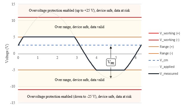
La combinaison des deux signaux culmine à +12,5 V, ce qui dépasse la tension de fonctionnement maximale. Le dépassement de la tension de fonctionnement maximale met en péril la validité des données sur d’autres voies multiplexées en raison d’une charge excessive sur le multiplexeur n’ayant pas suffisamment de temps pour se stabiliser.
Voir aussi
Monotonicité
La monotonicité est la garantie que lorsque les codes C N/A augmentent, la tension de sortie augmente également.
Exemple
Le NI PXIe-6363 garantit que la tension de sortie augmente à mesure que les codes C N/A augmentent. Par exemple, une fonction de rampe augmentera ou diminuera toujours selon la direction de la rampe.
Courant effectif en sortie
Pour la sortie analogique, le courant effectif en sortie est la quantité maximale de courant que le périphérique peut absorber ou générer. La charge connectée, y compris l’impédance de sortie, combinée à la tension programmée détermine le courant qui sera nécessaire pour maintenir la tension de sortie programmée.
La tension de sortie programmée est garantie si le courant effectif reste inférieur au courant effectif en sortie spécifié. Le dépassement du courant effectif en sortie met le périphérique dans un état de surcharge, où la tension de sortie n’est plus garantie.
Exemple
Le NI PXIe-6363 est capable de générer ± 5 mA à partir de n’importe quelle voie de sortie analogique. Sur la plage ± 10 V, cela signifie que l’impédance totale la plus basse qui peut être générée à pleine échelle est déterminée à partir de la puissance de sortie la plus élevée, ou de la tension et du courant le plus grand :

Compte tenu de l’impédance de sortie du PXIe-6363, l’impédance connectée la plus basse pouvant être générée à pleine échelle est la différence de la charge minimale et de l’impédance de sortie :

Voir aussi
Impédance en sortie
L’impédance en sortie est l’impédance effectivement en série avec une voie de sortie analogique, comme illustré ci-dessous :
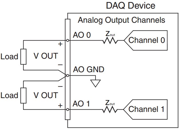
Une faible impédance de sortie permet à une plus grande tension générée de tomber à travers la charge de la sortie analogique. Il est important de prendre en compte l’impédance en sortie pour s’assurer que le niveau de tension souhaité est atteint
Exemple
Le NI PXIe-6363 a une impédance en sortie de 0,2 Ω. Cela signifie que si une charge connectée a une impédance de 500 Ω et que la tension spécifiée par l’utilisateur est de 1 V, la tension réelle sur la charge serait de 0,9996 V, ou 0,4 mV, inférieure à celle attendue. À cette tension, 1,99 mA sera également tiré sur l’appareil.
Courant de surcharge (court-circuit)
Si la combinaison de l’impédance en sortie et de la charge est trop faible, de sorte que plus de courant est tiré du périphérique que ce qui est spécifié par le courant effectif en sortie, le périphérique passe dans un état de surcharge. Le courant effectif, ou court-circuit, est la quantité maximale de courant que le périphérique pourra générer sans dommage. Dans cet état de surcharge, la tension baisse pendant que la génération de courant augmente.
Le dépassement du courant de surcharge risque d’endommager le périphérique. NI recommande d’utiliser à tout moment le périphérique dans la spécification du courant effectif en sortie pour éviter d’endommager le périphérique.
Exemple
Le NI 6363 a une spécification de courant de surcharge de 26 mA. Le dépassement de cette valeur, par exemple lors d’un court-circuit, peut endommager le périphérique.
Voir aussi
Protection contre les surcharges
Pour la sortie analogique, la protection contre les surcharges est la tension maximale qui peut être tolérée sur la voie avant que le périphérique ne soit endommagé. Cette spécification est supérieure à la tension réelle qui peut être programmée en cas de tension arrière accidentelle.
Exemple
Le NI PXIe-6363 est protégé jusqu’à ± 25 V sur chaque voie de sortie analogique individuellement. Cela signifie que, quelle que soit la tension programmée pour la sortie, tant que la tension à la broche par rapport à la sortie analogique GND est à ± 25 V, aucun dommage ne se produira sur le périphérique. Le dépassement de cette valeur risque d’endommager le périphérique.
Protection contre les surtensions
Le circuit d’entrée analogique a des diodes de protection en place qui déclencheront une tension élevée d’endommager les composants les plus critiques du périphérique, tels que le PGIA ou le C A/N.
- Lorsque le périphérique est allumé, ces diodes sont polarisées à une tension positive et négative, ce qui signifie qu’une tension supérieure à la somme de la polarisation et de la tension inverse doit être présente avant que ces diodes ne soient surchargées et puissent être endommagées.
- Lorsque le périphérique est éteint, la tension de polarisation est supprimée, de sorte que la tension nécessaire pour inverser les diodes est inférieure, ce qui rend le périphérique plus susceptible d’être endommagé.
Lorsqu’il est dans un état de surtension, la quantité maximale de courant qu’un périphérique peut absorber est spécifiée par le courant d’entrée pendant la condition de surtension.
Exemple
Le NI PXIe-6363 a une protection jusqu’à ± 25 V pour deux broches d’entrée analogique. Si plus de deux broches d’entrée analogique subissent une surtension supérieure à ± 25 V, le périphérique peut être endommagé. Lorsque le périphérique est éteint, le niveau de protection est inférieur à ± 15 V.
État au démarrage
L’état au démarrage spécifie la valeur d’une voie de sortie analogique lorsque le périphérique est sous tension et après une période d’impulsion transitoire connue sous le nom d’impulsion transitoire de marche/arrêt. Avant que le périphérique ne soit alimenté par le bus, la valeur sur la sortie est décrite dans la spécification d’impulsion transitoire de marche.
Exemple
Le NI PXIe-6363 aura ± 5 mV sur les voies de sortie analogiques à la mise sous tension.
Impulsion transitoire de marche/arrêt
Lors de l’application et de la mise hors tension du périphérique, il y a un signal d’impulsion transitoire sur les voies de sortie analogiques.
- Amplitude de l’énergie de l’impulsion transitoire : amplitude de crête atteinte par un signal d’impulsion transitoire pendant une période d’impulsion transitoire
- Durée d’énergie de l’impulsion transitoire : la durée pendant laquelle le signal de l’impulsion transitoire s’atténue dans l’état de marche
Exemple
Le NI PXIe-6363 a une impulsion transitoire spécifiée de 1,5 V pk pendant 200 ms. Le NI USB-6363 a une impulsion transitoire spécifiée de 1,5 V pk pendant 1,2 s. La période d’impulsion transitoire sur les périphériques USB peut être plus longue que celle spécifiée en raison des mises à jour du firmware et des performances de l’hôte USB.
Plage (entrée ou sortie)
Pour l’entrée analogique, il s’agit de la valeur positive et négative maximale qui peut être mesurée avec une précision garantie. Pour la sortie analogique, il s’agit de la valeur maximale positive ou négative pouvant être générée. Certains périphériques ont plusieurs plages d’entrée ou de sortie qui peuvent être utilisées pour fournir une résolution plus élevée à des signaux de niveau inférieur.
Exemple
Le NI PXIe-6363 a quatre plages de tension d’entrée : ± 0,1 V, ± 0,2 V, ± 0,5 V, ± 1 V, ± 2 V, ± 5 V, ± 10 V. Il a une plage de sortie : ± 10 V.
Voir aussi
Résolution du convertisseur analogique/numérique (C A/N)
Résolution du convertisseur numérique/analogique (C N/A)
Fréquence d’échantillonnage
La fréquence d’échantillonnage spécifie la fréquence à laquelle un C A/N convertit les données des valeurs analogiques en valeurs numériques. Certains périphériques n’ont qu’un seul C A/N, donc la fréquence d’échantillonnage est partagée entre les voies tandis que d’autres périphériques ont un C A/N dédié par voie. La fréquence d’échantillonnage est mesurée en échantillons par seconde (S/s) ou en échantillons par seconde par voie (S/s/voie) lors de l’acquisition à partir de plusieurs voies.
- Maximum de voie unique : pour une fréquence d’échantillonnage partagée sur plusieurs voies, une seule voie peut acquérir des données à un taux plus élevé que celui autorisé lors du partage
- Maximum multivoies : pour un périphérique qui partage la fréquence d’échantillonnage entre les voies, il s’agit de la vitesse maximale à laquelle toutes les voies combinées peuvent acquérir des données
- Minimum : la vitesse minimale à laquelle les données peuvent être acquises
Pour l’équivalent de sortie analogique, voir Fréquence de mise à jour maximale.
Exemple
Le NI PXIe-6363 est un périphérique multiplexé, ce qui signifie que les voies d’entrée analogiques sont multiplexées en un seul C A/N. Une seule voie d’entrée analogique peut échantillonner des voies analogiques jusqu’à 2 millions d’échantillons par seconde (2 MS/s). Lorsque vous utilisez plusieurs voies, le débit combiné de toutes les voies doit être inférieur à 1 MS/s (2 voies peuvent échantillonner à 500 kéch./s/voie, 4 voies peuvent échantillonner à 250 kéch./s/voie, etc.). Il n’y a pas de fréquence d’échantillonnage minimale pour ce périphérique.
Mémoire de la liste de balayage
Le nombre de voies balayées dans une tâche est spécifié comme mémoire de la liste de balayage. Une tâche d’entrée analogique peut contenir de nombreuses voies virtuelles dans une séquence connue comme liste de balayage. La liste de balayage peut contenir plusieurs fois la même voie physique et des échantillons peuvent être prélevés dans n’importe quel ordre arbitraire. Lorsque la tâche est validée, cette liste de balayage est temporairement programmée sur le périphérique DAQ.
Exemple
Le NI PXIe-6363 possède une mémoire de liste de balayage de 4 095 entrées. Cela signifie qu’un balayage ou un repère de l’horloge d’échantillonnage peut déclencher jusqu’à 4 095 voies physiques en cours de lecture lorsque toutes les voies physiques sont contenues dans une seule tâche. Cependant, en gardant à l’esprit le temps de stabilisation des mesures multivoies (également appelé intervalle de conversion pour certains périphériques), cela limiterait la fréquence d’horloge d’échantillonnage à un maximum d’environ 250 Hz.
Temps de stabilisation
Temps nécessaire à une valeur de sortie analogique pour se stabiliser à un certain degré de précision.
Exemple
Le NI PXIe-6363 a un temps de stabilisation d’une étape pleine échelle à 1 LSB ou 15 ppm de 2 µs. Cela signifie que pour une oscillation pleine échelle sur la plage ± 5 V (-5 V, 5 V, -5 V, 5 V, etc.), la fréquence maximale pouvant être générée à 1 LSB près est de 1/(2 µs) = 500 kHz.
Temps de stabilisation pour les mesures multivoies
Durée pendant laquelle le C A/N doit être connecté à chaque voie lors de l’exécution d’une acquisition multivoie.
Exemple
Lors de l’acquisition de données sur le NI PXIe-6363 dans une plage de ± 10 V, le multiplexeur doit rester sur une seule voie jusqu’à 1,5 µs pour que l’amplificateur d’instrumentation à gain programmable (NI-PGIA) se stabilise à 1 bit de poids faible (LSB) de la valeur réelle avec une entrée de pas pleine échelle fournie.
Vitesse de variation
Le taux de variation spécifie le taux de changement pour les voies de sortie analogiques dans un périphérique donné. Elle est généralement mesurée en V/µs. Le temps de stabilisation pour la sortie est calculé avec le temps de variation déjà inclus dans le calcul. Il est important de prendre en compte la vitesse de variation lors de la conception d’un système pour les signaux haute fréquence de haute amplitude, car la grande oscillation de l’amplitude peut dépasser la vitesse de variation pour un périphérique donné.
Exemple
Le NI PXIe-6363 a une vitesse de variation typique de 20 V/µs, ce qui signifie que la haute fréquence à pleine échelle pouvant être générée est de 1 MHz. Tenter de produire un signal pleine échelle avec une amplitude plus élevée entraînera une distorsion indésirable.
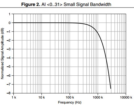
Bande passante de petit signal
Plage de fréquences qui est transmise avec une atténuation inférieure à –3 dB. Les tests pour la bande passante de petit signal sont effectués avec des signaux basse tension afin que la distorsion de la vitesse de variation ne soit pas un facteur.
Exemple
Le NI PXIe-6363 a une bande passante de petit signal de 1,7 MHz, comme indiqué ci-dessous :
Gamme dynamique sans bruit (SFDR)
La gamme dynamique sans bruit est la gamme dynamique utilisable avant que le bruit parasite n’interfère ou ne déforme le signal fondamental. Les circuits d’entrée analogique et de sortie analogique ont tous deux des non-linéarités qui entraînent une distorsion harmonique. La SFDR est facilement observable dans le domaine fréquentiel comme :
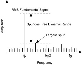
Exemple
Le PCI-6133 a un SFDR d’environ 95 dB. En prenant le graphique ci-dessous à titre d’exemple, si le signal fondamental était appliqué à 0 dB, le parasite suivant le plus élevé se produirait à 95 dB plus bas : fournissant une gamme dynamique utilisable sans interférence parasite.
Précision du cadencement
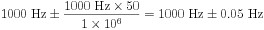
Lors de la génération d’un signal d’horloge sur un périphérique NI DAQ pour les signaux de cadencement, la fréquence réelle générée sera dans la précision de cadencement. Cette spécification est dérivée de la précision globale de l’oscillateur à quartz embarqué. La précision de cadencement est généralement mesurée en parties par million (ppm). Pour convertir cette valeur de précision en Hz, multipliez par la valeur de précision divisée par 1 million. La fréquence de l’horloge ne devrait pas changer radicalement d’un cycle à l’autre.
Exemple
Le PXIe-6363 a une précision de cadencement de 50 ppm. Pour une tâche de sortie analogique avec une fréquence de mise à jour de 1 000 S/s, l’horloge d’échantillonnage fonctionnera à 1 000 Hz ± 50 ppm. En Hz, cela se traduit par :
Résolution du cadencement
Les fréquences de mise à jour et d’échantillonnage pour les tâches d’entrée et de sortie analogiques sont limitées à des valeurs discrètes lors de l’utilisation d’un moteur de cadencement intégré. La différence de périodes d’horloge entre deux débits adjacents est connue sous le nom de résolution de cadencement. NI-DAQmx contraindra une fréquence sélectionnée jusqu’à la prochaine fréquence disponible s’il ne peut pas générer la fréquence exacte spécifiée par l’utilisateur.
Exemple
Le NI PXIe-6363 a une résolution de cadencement spécifiée de 10 ns. Cela signifie qu’il peut générer ou acquérir des données à des multiples entiers de 10 ns. Par exemple, 32 000,00 Hz et 32 010,2432… Hz sont deux fréquences adjacentes, car leurs périodes d’horloge sont respectivement de 31,250 µs et 31,240 µs. Pour trouver la prochaine fréquence disponible, ajoutez ou soustrayez la résolution de cadencement à une période d’horloge connue.
Distorsion harmonique totale (DHT)
En raison des non-linéarités inhérentes aux composants C A/N et C N/A, des fréquences harmoniques apparaîtront dans les signaux mesurés ou générés. Le rapport de la somme des puissances de ces harmoniques à la puissance du fondamental est connu sous le nom de distorsion harmonique totale.
Exemple
Le PCI-6133 a un THD spécifié d’environ -101 dB. Cela signifie que pour un signal de test donné, dans ce cas un signal sinusoïdal de 10 kHz à pleine échelle, la puissance du signal attribuée à la distorsion harmonique est inférieure à 0,001 %. Inversement, plus de 99,999 % de la puissance mesurée peut être attribuée au ton fondamental ou au signal d’intérêt.
Spécifications du sous-système numérique
Les périphériques et modules NI MIO DAQ peuvent prendre en charge une entrée numérique, une sortie numérique ou une combinaison des deux systèmes. Ils prennent également en charge les lignes PFI (Programmable Function Interface), qui permettent d’acheminer les signaux numériques à travers le fond de panier. Ce qui suit est une liste de spécifications communes, leur définition et comment cette spécification peut être utilisée dans le monde réel.
Fréquence d’horloge d’échantillonnage d’entrée numérique
Détermine la vitesse à laquelle vous pouvez acquérir des données de waveform numérique. Cette spécification est différente selon si le périphérique est basé sur USB ou PCI (y compris PCI, PCI Express, PXI et PXI Express). En règle générale, les périphériques PCI permettront des vitesses de transfert de waveform numérique plus élevées en raison du débit soutenu plus élevé du bus, de la latence plus faible et de l’implémentation de transferts de données DMA (Direct Memory Access).
Exemple
Le NI 6363 se présente sous trois formes : USB, PCI Express et PXI Express.
- USB : la fréquence d’horloge d’échantillonnage peut varier de 0 à 1 MHz, en fonction de l’activité d’autres périphériques sur le bus. Par exemple, si vous enregistrez des données sur un disque dur externe USB sur le même concentrateur USB que votre périphérique, vous ne pourrez peut-être pas atteindre la vitesse d’acquisition complète de 1 MHz. Pour des performances maximales, NI recommande que le périphérique USB DAQ soit le seul périphérique sur un concentrateur racine USB.
- PCI Express et PXI Express : la fréquence d’horloge d’échantillonnage peut varier de 0 à 10 MHz, en fonction de l’activité d’autres périphériques sur le bus. Par exemple, si une grande quantité de données est envoyée à un GPU pour un traitement parallèle au cours d’une acquisition, il se peut que vous ne puissiez pas atteindre la vitesse d’acquisition complète de 10 MHz. Pour des performances maximales, NI recommande que lorsqu’un périphérique PCI Express ou PXI Express se trouve sur le même commutateur que d’autres périphériques, tous les périphériques envoient des données dans la même direction.
Fréquence d’horloge d’échantillonnage de sortie numérique
Détermine la vitesse à laquelle vous pouvez sortir des données de waveform numérique à partir du port 0 sur la plupart des périphériques NI. Cette spécification est différente selon si le périphérique est basé sur USB ou PCI (y compris PCI, PCI Express, PXI et PXI Express), et de l’origine des données.
- Régénérer à partir de FIFO : un utilisateur écrit des données sur le périphérique une seule fois et les données sont régénérées à bord du périphérique. Cette méthode élimine les problèmes de trafic de bus et entraîne une vitesse de sortie plus élevée.
- Streaming depuis la mémoire : le périphérique ne régénère pas les données, il doit donc toujours y avoir de nouvelles données disponibles à partir de l’application de l’utilisateur pour éviter une erreur de dépassement. Cette méthode se traduit par une communication constante sur le bus, donc les vitesses de mise à jour sont plus limitées sur les bus à débit inférieur.
Exemple
Le NI 6363 se présente sous trois formes : USB, PCI Express et PXI Express.
- USB : comparé à PCI Express et PXI Express, il s’agit d’un bus à faible débit et à latence plus élevée. Lors de la régénération d’un waveform en sortie à partir du FIFO, la fréquence de mise à jour maximale de 10 MHz peut être atteinte. Lors du streaming depuis la mémoire, les données doivent être transmises via USB, et une fréquence maximale plus lente de 1 MHz est donc spécifiée.
- PCI Express et PXI Express : ces bus sont plus rapides et peuvent supporter un débit plus élevé, fournissant une fréquence de mise à jour maximale de 10 MHz spécifiée.
Paramètres de filtre anti-rebonds
Lorsqu’une ligne numérique change d’état (faible/élevé ou élevé/faible), elle se stabilise parfois entre les deux états avant de s’établir sur le nouvel état. Un filtre anti-rebonds peut être implémenté pour ignorer le balancement et lire uniquement une valeur une fois stabilisé. Pour les lignes d’entrée numériques statiques (PFI/Port 1/Port 2), le filtre anti-rebonds numérique est utilisé pour stabiliser des signaux bruyants ou parasites comme ceux qui proviennent souvent d’interfaces physiques comme les boutons-poussoirs. Ces filtres peuvent être personnalisés par l’utilisateur pour n’importe quelle longueur de filtre, contrairement au filtre de ligne numérique.
Exemple
Le PXIe-6363 permet un cadencement d’intervalle de 90 ns, 5,12 µs, 2,56 ms ou personnalisé pour le filtre. Il permet également des transitions hautes et basses programmables et peut être sélectionné par ligne d’entrée. Ces temps de filtrage sont dérivés d’un oscillateur embarqué sur le PXIe-6363.
Hystérésis Delta VT (VT+ - VT-)
L’hystérésis est la propriété d’avoir un seuil de transition différent selon que la valeur augmente ou diminue. Dans ce cas, la transition observée est de l’état élevé à indéterminé et de l’état faible à indéterminé. La différence entre le seuil positif et le seuil négatif est l’hystérésis du seuil de tension. Cette spécification illustre à quel point le niveau de tension peut dépasser en dessous ou au-dessus du seuil avant d’entrer à nouveau dans l’état indéterminé.
Exemple
Le NI PXIe-6363 spécifie une hystérésis d’au moins 0,2 V. Cela signifie que si un signal passe de 0 à 5 V, il peut chuter d’au plus 0,2 V en dessous de la valeur VT+ avant que le niveau logique puisse être considéré comme faible. Pendant cette période variable, la valeur traversera l’état indéterminé.
Filtre de ligne numérique
Lorsqu’un filtre de ligne est activé sur n’importe quelle ligne du port 0, cette ligne doit maintenir un niveau logique stable pendant la durée de filtrage spécifiée afin d’être enregistrée en tant que niveau logique. Il s’agit d’un outil utile pour transmettre des données numériques sur de longs câbles ou dans des environnements bruyants. Il existe généralement différents temps de filtrage qui peuvent être sélectionnés dans le logiciel : un filtre court, moyen et long. Selon les caractéristiques du bruit dans votre système, l’un de ces temps de filtrage peut être plus approprié pour votre application.
Exemple
Le PXIe-6363 possède trois temps de filtre de ligne numérique intégrés : 160 ns, 10,24 µs et 5,12 ms. Veuillez noter que ces filtres s’appliquent uniquement aux lignes du port 0. Pour les options de filtrage sur les ports 1 et 2, les lignes PFI ou les lignes spécifiques PXI, voir Paramètres de filtre anti-rebonds.
Commande de direction
Détermine si une ligne numérique ou PFI peut être configurée comme ligne d’entrée ou de sortie.
Exemple
Le PXIe-6361 permet de configurer chaque ligne numérique ou PFI en entrée ou en sortie.
Référence de masse (numérique)
Spécifie le point de référence selon lequel les signaux numériques seront mesurés ou générés. Par exemple, une sortie numérique de niveau de logique haut peut mesurer 5 volts entre la broche de sortie et la référence de masse spécifiée.
Exemple
Le PXIe-6361 utilise le signal de masse numérique (D GND) comme référence de masse pour les signaux d’entrée numérique, de sortie numérique et de ligne PFI. La masse numérique est séparée de la masse analogique pour éviter les interférences introduites par le mélange de signaux de différents niveaux et fréquences. Les masses numérique et analogique sont référencées à la masse du châssis. Des précautions supplémentaires doivent être prises pour les périphériques USB, car les masses analogiques et numériques sont référencées à la masse du châssis de l’ordinateur via le blindage du câble USB.
Courant d’entrée élevé/Courant d’entrée faible (IIH/IIL)
Idéalement, l’impédance d’entrée d’un appareil est infinie et aucun courant ne sera consommé, mais cela n’est pas réalisable en pratique. Lors de la lecture d’une valeur numérique à 0 V ou 5 V, une petite quantité de courant sera tirée par le circuit d’entrée numérique du périphérique NI. La quantité de courant tirée lors de la mesure d’un niveau de tension élevé est un courant élevé d’entrée, de même la quantité de courant tirée lors de la mesure d’un niveau de tension faible est un courant faible d’entrée. Il est important de s’assurer qu’un signal numérique mesuré a la capacité de tolérer les valeurs actuelles spécifiées.
Exemple
Le NI PXIe-6363 fournira jusqu’à 10 µA lorsque Vin = 0 V ou descendra jusqu’à 250 µA lorsque Vin = 5 V. Cela s’applique à toutes les lignes numériques et PFI.
Entrée haute tension/entrée basse tension (VIH/VIL)
Les plages de tension de fonctionnement recommandées qu’un signal en entrée devrait être afin d’enregistrer un niveau de logique haut et un niveau de logique bas. Cette spécification définit les conditions de fonctionnement recommandées afin que l’utilisateur sache de quelles valeurs doit être son signal, alors que VT+ et VT- sont les spécifications du périphérique lui-même.
Exemple
Le NI PXIe-6363 spécifie que la tension d’entrée qui sera enregistrée en tant que signal bas va de 0 à 0,8 V. Pour un signal haut, cette plage est de 2,2 à 5,25 V. En dessous de 0 V et au-dessus de 5,25 V, le périphérique est dans un état de protection contre les surtensions. Il existe également une plage indéterminée où un changement de faible à élevé ou élevé à faible n’est enregistré que lorsqu’il dépasse VIH ou VIL.
Voir aussi
Seuil positif (VT+)/seuil négatif (VT-)
Protection de la tension d’entrée (numérique)
Protection de la tension d’entrée (numérique)
Les lignes d’entrée numériques individuelles ont une protection d’E/S dédiée contre les décharges électrostatiques (ESD) et les conditions de surtension. Pour une sécurité supplémentaire du périphérique, un deuxième niveau de protection est partagé entre toutes les lignes numériques et PFI. Une surtension excessive sur plusieurs lignes en même temps sollicite ce circuit de protection partagé et peut endommager le périphérique.
Exemple
Le NI PXIe-6363 a une protection de tension d’entrée de ± 20 V sur jusqu’à deux broches en même temps. Cette disposition signifie que chaque ligne peut gérer individuellement jusqu’à ± 20 V de surtension en toute sécurité, mais pas plus de deux lignes à la fois ne peuvent dépasser la tension d’entrée nominale.
Voir aussi
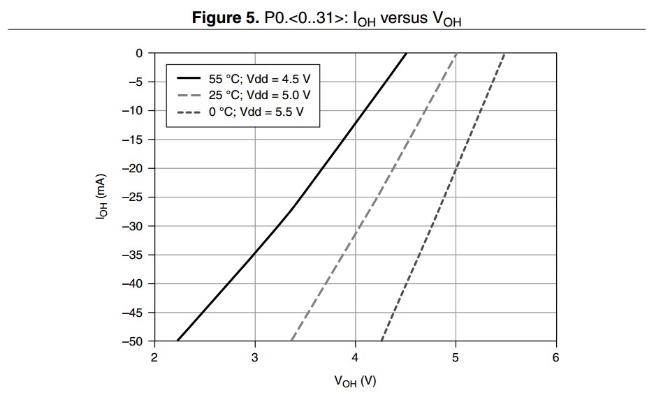
Sortie de courant élevé/sortie de courant faible (IOH/IOL)
Lors de la sortie d’une valeur élevée ou faible, les tensions nominales pour la plupart des périphériques NI sont 0 et 5 V. Cependant, si une charge à impédance relativement faible est connectée, une demande de courant plus élevée est présente et cette tension nominale passera à 0 V ou chutera à 5 V. Cette spécification caractérise la relation entre le courant de sortie et la tension de sortie.
Exemple
Le PXIe-6363 est capable de fournir ou d’abaisser le courant selon si une valeur élevée ou faible est écrite sur la broche. Pour le port 0, la valeur maximale recommandée pour le courant injecté et absorbé est de 24 mA par ligne. Lorsque le courant quitte le périphérique (injecté), le courant est indiqué comme -24 mA. Lorsque le courant entre dans le périphérique (absorbé), le courant est indiqué comme +24 mA. Consultez le graphique ci-dessous pour connaître les caractéristiques de la quantité de courant qui peut être tirée à une température et une tension de sortie données.
Port/Taille de l’échantillon
Lors de l’acquisition ou de la génération de waveforms numériques, le nombre de lignes dans le port 0 définit la taille de l’échantillon. Pour limiter la quantité de trafic sur le bus, si un échantillon contient une combinaison de lignes 0 à 7, la taille de l’échantillon sera de 1 octet. De même, si un échantillon contient uniquement les lignes 0 à 15, la taille de l’échantillon est réduite à 2 octets. Cela continue jusqu’au nombre maximum de lignes dans le port, jusqu’à la taille entière du port.
Exemple
Le NI PXIe-6363 possède 32 lignes sur le port 0. Cela signifie qu’un seul échantillon numérique fait jusqu’à 32 bits (4 octets).
Seuil positif (VT+)/seuil négatif (VT-)
Lors de l’entrée d’un signal logique dans le périphérique, la valeur à laquelle un signal passera de la plage indéterminée à la plage de niveau de logique haut est connue comme le seuil positif. Inversement, le seuil négatif est le niveau de tension qui doit être franchi pour enregistrer un niveau de logique bas. Le seuil positif sera toujours supérieur au seuil négatif. Il est important de s’assurer que votre signal franchit définitivement ces deux niveaux pour enregistrer avec précision les états numériques. Ces spécifications renvoient au périphérique lui-même, tandis que les tensions d’entrée haute et basse renvoient aux conditions de fonctionnement recommandées.
Exemple
Le NI PXIe-6363 a un VT+ de 2,2 V maximum et un VT- d’au moins 0,8 V.
Voir aussi
Résistance de pull-down/pull-up
Certains périphériques NI sont capables de configurer par programmation leurs lignes numériques ou PFI en entrée, en sortie ou en haute impédance. Les résistances de traction sont utilisées pour garantir que toute broche qui serait autrement flottante est référencée à un signal connu, comme la masse ou une source de tension. Une résistance de pull-down tirera un signal flottant à un état de masse ou un niveau de logique bas, et une résistance pull-up tirera un signal flottant à la valeur de tension de niveau de logique haut.
Exemple
Le PXIe-6361 utilise une résistance de pull-down de 50 kΩ qui garantit que les terminaux qui ne sont pas activement entraînés à l’état haut ou bas flotteront à un état bas.
FIFO acquisition de waveforms (entrée numérique)
Lors de la lecture des données de waveform numérique, il existe un élément de stockage temporaire à bord du périphérique qui bufférise les données, appelé FIFO. DAQmx copie les données de ce FIFO dans un bloc de mémoire en RAM, connu sous le nom de buffer du PC. De là, un logiciel de développement, tel que LabVIEW, copie les données dans la mémoire de l’application. La taille de ce FIFO et la vitesse de stockage des données déterminent la fréquence à laquelle le driver DAQmx copiera les données pour éviter un dépassement.
Exemple
Le NI PXIe-6363 possède un FIFO d’acquisition de waveform numérique de 255 échantillons. Cela signifie que si vous acquérez des données à un débit de 100 kbit/s, le FIFO intégré déborderait en environ 2,5 ms si le driver DAQmx ne transférait pas les données dans le buffer du PC.
FIFO de génération de waveforms (sortie numérique)
Il existe un stockage temporaire à bord des périphériques MIO qui bufférise les points de données dans une structure de données premier entré, premier sorti appelée FIFO. Ce stockage est particulièrement utile pour les périphériques USB où les transferts sur le bus prennent plus de temps, en particulier lorsque de nombreux périphériques partagent le même concentrateur racine USB. Si un seul pattern numérique est nécessaire, il peut être chargé sur ce FIFO pour éviter de transférer les données sur le bus plusieurs fois. En utilisant l’API DAQmx, un utilisateur peut programmer pour l’un de ces cas.
Exemple
Le NI PXIe-6363 possède un FIFO de génération de waveforms numériques de 2047 échantillons. Par exemple, si vous utilisez la sortie numérique pour la communication I2C à un débit de 100 kbit/s, le FIFO entier sera émis en 20 ms. Cela signifie que l’utilisateur doit appeler DAQmx - Écrire plus fréquemment que cela pour continuer à diffuser des données vers le FIFO. Si vous effectuez des tests de débit de données, un seul pattern peut être chargé dans le FIFO à l’aide de l’API DAQmx et sorti à différents débits de données sans jamais avoir à écrire de nouvelles données sur le bus PCI Express.
Caractéristiques du compteur
Précision de l’horloge de base (compteurs à usage général)
La précision d’une horloge de base interne a un impact direct sur la précision de toute mesure ou génération de fréquence à partir d’un compteur à usage général. Cette précision est également héritée de la précision globale de la base de temps du périphérique, ce qui signifie que la précision de cette horloge peut être améliorée si une base de temps principale plus précise est fournie en externe.
Exemple
Le PXIe-6363 a une précision d’horloge de base de 50 ppm. Si un utilisateur souhaite générer une horloge à fonctionnement libre de 12,8 MHz avec ce module, le calcul suivant peut être utilisé pour déterminer la précision :

Cette erreur peut être améliorée avec l’utilisation d’une horloge de base externe de plus grande précision, ou d’un périphérique avec une meilleure précision d’horloge de base, comme le PXIe-6614. Le PXIe-6614 utilise un oscillateur thermostaté (OCXO) plus précis et stable qui est moins sensible aux variations de température, avec une précision d’horloge de base dans le pire des cas de 75 ppb. Si le même signal devait être généré sur ce module, la fréquence réelle serait :

Résolution du compteur
Nombre de bits qu’un compteur peut utiliser pour représenter un nombre. Lorsqu’un compteur à usage général est configuré pour émettre une impulsion, la durée pendant laquelle l’impulsion est active est représentée par la valeur dans le registre du compteur. La combinaison de cette valeur et de la vitesse de comptage du compteur (définie par l’horloge de base du compteur) détermine la largeur d’impulsion maximale qui peut être atteinte. De même, lorsque vous utilisez un compteur pour mesurer la largeur d’impulsion d’un signal, la largeur d’impulsion maximale qui peut être enregistrée est déterminée par l’horloge de base du compteur et la résolution du compteur. Si un signal dépasse la largeur d’impulsion maximale, le compteur basculera et l’API NI-DAQmx renverra une erreur. Pour cette raison, il est important de savoir comment calculer les paramètres de signal maximum.
Les compteurs avec une résolution plus élevée offrent plus de flexibilité lors du compromis entre la résolution et la longueur des mesures/générations. Reportez-vous au graphe ci-dessous pour plus de détails sur ce compromis.
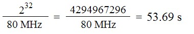
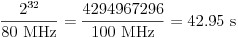
Exemple
Le PXIe-6614 utilise des compteurs 32 bits pour les tâches d’entrée et de sortie compteur. Si une tâche d’entrée compteur est configurée pour mesurer la largeur d’impulsion, nous pouvons calculer la largeur d’impulsion maximale qui peut être mesurée en calculant la valeur maximale du compteur et en la divisant par la fréquence d’horloge de base interne du compteur. L’horloge de base du compteur à 100 MHz permettra une précision de 10 ns, de sorte que l’horloge de base sera sélectionnée pour cet exemple.
Fréquence de l’horloge de base externe (compteurs à usage général)
Si une fréquence d’horloge de base spécifique est nécessaire, la plupart des périphériques NI MIO autorisent l’utilisation d’une horloge de base externe. Cette horloge remplit les mêmes fonctions qu’une horloge de base interne, mais est fournie en externe par l’utilisateur. La fréquence maximale d’une horloge de base externe dépend du bus du périphérique en raison des limitations de bande passante.
Exemple
Le NI 6363 est disponible en plusieurs facteurs de forme qui ont des exigences différentes pour une horloge de base externe.
- PCI Express et USB : la plage de fréquences pour les horloges de base externes va de 0 à 25 MHz, entrée sur n’importe quelle ligne PFI. La limitation de la fréquence maximale est due à la bande passante d’une ligne PFI.
- PXI Express : le PXIe-6363 tire parti des capacités avancées d’un châssis PXI Express et autorise jusqu’à 100 MHz de signal sur les lignes différentielles en étoile (DSTAR).
FIFO (compteur à usage général)
L’élément de mémoire premier entré, premier sorti (FIFO) à bord des périphériques MIO est utilisé pour buffériser des échantillons de données pour les applications d’entrée ou de sortie. Pour les applications d’entrée compteur, des points de données tels que la valeur du compteur à des intervalles spécifiques sont stockés dans le FIFO avant que DAQmx transfère automatiquement les données vers un bloc pré-alloué de RAM PC. Le FIFO est utilisé pour les applications de sortie compteur afin de stocker une séquence de valeurs de rapport cyclique et de fréquence pour modifier la forme de la waveform générée. Un FIFO plus grand est utile car il réduit la quantité de trafic sur le bus de données étant donné que de plus grands blocs de données peuvent être transférés moins fréquemment que les périphériques avec un FIFO plus petit.
Exemple
Le PXIe-6614 a un FIFO pour chaque compteur qui stocke 127 échantillons, permettant de configurer 127 paramètres différents pour une génération de train d’impulsions avant que des transferts supplémentaires sur le bus ne soient nécessaires.
Horloges de base internes (compteurs à usage général)
L’horloge de base interne d’un compteur est le signal qui fera augmenter ou diminuer la valeur du compteur en fonction de l’état du terminal de porte. La période de cette horloge détermine la résolution en secondes d’un signal mesuré ou généré, mais détermine également la vitesse à laquelle le compteur basculera lors de la mesure ou de la génération d’impulsions longues. Pour toute mesure ou application de compteur, il existe une erreur de quantification de période de base de temps ± 1. Pour minimiser la quantité d’erreur de quantification, il est important de sélectionner l’horloge de base la plus rapide possible pour votre application.
Exemple
Lorsque vous effectuez une mesure à l’aide du PXIe-6614, les trois horloges de base internes qui peuvent être utilisées ont des vitesses de 100 kHz, 20 MHz et 100 MHz. Ces horloges de base fournissent une résolution allant de 10 µs à 10 ns. Si un signal PWM de 125 kHz et un rapport cyclique de 35 % est appliqué, la largeur d’impulsion réelle en secondes est de 2,8 µs. Elle est inférieure à la résolution de l’horloge de base de 100 kHz et ne peut donc pas être utilisée pour cette mesure. L’horloge de 20 MHz a une résolution de 50 ns, elle peut donc parfaitement mesurer la durée de ce signal impulsion d’horloge de base ± 1. Il en résulte une mesure de 2,8 µs ± 0,05 µs, soit une erreur d’environ 1,8 %. Cette même mesure sur l’horloge 100 MHz se traduira par une mesure de 2,8 µs ± 0,01 µs pour une erreur de 0,36 %. Dans ce cas, l’horloge de 100 MHz peut mesurer une largeur d’impulsion jusqu’à environ 43 secondes avant le retournement du compteur, donc cette largeur d’impulsion de 2,8 µs est bien en dessous de la limite maximale.
Voir aussi
Autres caractéristiques
Interface de bus
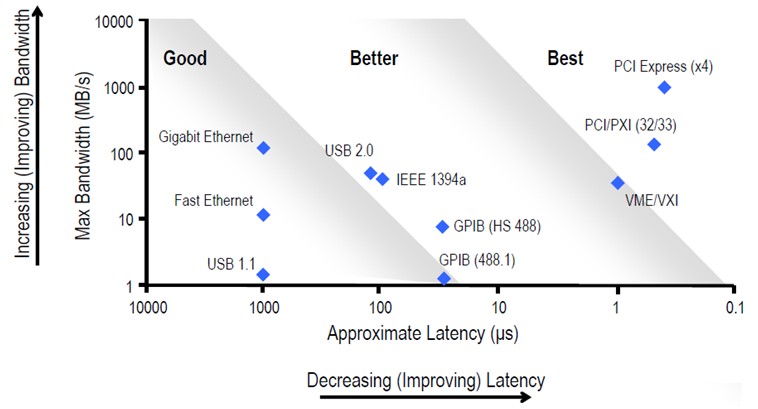
PCI, PCI Express, PXI, PXI Express et USB sont tous des exemples d’interfaces de bus qu’un périphérique MIO DAQ peut prendre. Ces bus fournissent des compromis clés entre la vitesse de transfert des données, la latence, la portabilité et le nombre de voies.
Exemple
Le NI 6363 est disponible en USB, PXI Express et PCI Express. Bien que ces périphériques et modules aient des fonctionnalités similaires, le module PXI Express et le périphérique PCI Express offrent une latence plus faible et un débit supérieur par rapport au périphérique USB. Le module PXI Express présente l’avantage supplémentaire du système PXI Express. Le périphérique USB a l’avantage d’être remplaçable à chaud et plus compact, ce qui le rend meilleur pour les applications mobiles.
Étalonnage
Comme tous les équipements de test et de mesure, il est important d’effectuer un étalonnage de routine pour garantir que le périphérique fonctionne dans les paramètres de précision spécifiés. Le périphérique a une certaine quantité d’auto-échauffement, il est donc important de permettre le temps de préchauffage spécifié avant de prendre des mesures pour s’assurer qu’une température stable est atteinte. À ce stade, il est recommandé que le périphérique soit auto-calibré s’il est pris en charge. Reportez-vous aux services d’étalonnage pour plus d’informations sur les services d’étalonnage proposés par NI.
Exemple
L’USB-6363 a un temps de préchauffage de 15 minutes et un intervalle d’étalonnage de 2 ans. NI recommande d’auto-étalonner le périphérique après 15 minutes de mise sous tension pour garantir une précision optimale. Après deux ans d’utilisation, NI recommande d’envoyer le périphérique pour un étalonnage certifié.
Limites d’intensité
Chaque périphérique MIO a une quantité maximale de courant qu’il peut absorber ou générer. Les spécifications de cette section sont une combinaison des courants d’absorption et d’injection. Certains périphériques ont un fusible à réinitialisation automatique sur la ligne utilisateur +5 V en cas de surtensions accidentelles. Des dommages au périphérique peuvent survenir si les spécifications de courant maximales sont dépassées.
Exemple
Si un PXIe-6363 génère le courant maximal de l’ensemble de ses 32 lignes DIO sur le port 0 (24 mA par ligne), la consommation totale de courant du port 0 sera de 0,768 A. S’il existe également un circuit connecté aux lignes utilisateur +5 V sur les connecteurs 0 et 1 qui tire 0,25 A de chaque connecteur, alors le module fournira une combinaison de 1,268 A. Les 0,25 A sont dans les 1 A max. de chaque connecteur d’alimentation et la consommation de 0,768 A des lignes DIO combinée avec les 0,5 A des lignes utilisateur +5 V se situent dans le maximum de 2 A de toutes les sorties combinées. Si cette même application devait être utilisée sur un PCIe-6363, le connecteur du lecteur de disque facultatif doit être connecté pour garantir que le périphérique fonctionne dans les limites d’intensité maximales.
Gestion de l’environnement
Pour plus d’informations sur l’engagement de NI à concevoir et fabriquer des produits d’une manière respectueuse de l’environnement, visitez la section Impact environnemental.
Déclenchements numériques externes
Les appareils MIO sont capables d’importer un signal de déclenchement numérique à partir de n’importe quelle ligne PFI et d’exporter également certains des signaux les plus courants utilisés sur le périphérique à des fins de synchronisation. Des signaux, tels que des horloges d’échantillonnage et des déclencheurs de démarrage, peuvent être émis par le périphérique MIO. Un filtre numérique peut être appliqué à n’importe lequel de ces signaux à l’aide de l’API DAQmx. Reportez-vous à la table de routage de votre périphérique dans NI MAX pour plus d’informations sur ces routes de déclenchement.
- Polarité : indique si le signal exporté ou importé est actif haut ou bas actif
Exemple
Le PXIe-6363 est capable de router le déclencheur de démarrage d’entrée analogique vers n’importe quelle ligne PFI, PXIe_DSTARA, PXIe_DSTARB, PXI_TRIG ou PXI_STAR qui n’a pas encore été réservée pour être utilisée par une autre tâche ou un autre périphérique. En regardant les routes de périphérique dans MAX, ce routage est également bidirectionnel, ce qui signifie que le périphérique peut accepter un déclencheur de démarrage d’entrée analogique à partir de l’une de ces mêmes sources.
Générateur de fréquence
En plus des compteurs à usage général qui existent sur les appareils MIO, il existe un compteur séparé avec des fonctionnalités limitées qui peut être utilisé comme générateur de fréquence. Sur un périphérique MIO typique, il existe un générateur de fréquence unique qui est limité à un nombre fini de fréquences pouvant être générées. Les fréquences qui peuvent être générées peuvent être utilisées pour fournir un signal d’horloge à un autre sous-système du périphérique, ou peuvent être exportées pour être utilisées par des circuits externes.
Exemple
Le PXIe-6363 possède une voie de générateur de fréquence qui peut prendre l’une des trois horloges de base (20 MHz, 10 MHz et 100 kHz) et la diviser par un diviseur de 1 à 16. Si un utilisateur souhaite générer un signal de 50,0 kHz, il peut sélectionner l’horloge de base de 100 kHz et un diviseur de 2, le tableau suivant montre une version tronquée des fréquences possibles.
| Diviseur | Horloge de base | ||
|---|---|---|---|
| 20 MHz | 10 MHz | 100 kHz | |
| 1 | 20 MHz | 10 MHz | 100 kHz |
| 2 | 10 MHz | 5 MHz | 50 kHz |
| 3 | 6,67 MHz | 3,33 MHz | 33,3 kHz |
| ... | |||
| 15 | 1,33 MHz | 0,67 MHz | 6,67 kHz |
| 16 | 1,25 MHz | 0,63 MHz | 6,25 kHz |
Température de fonctionnement
Spécifie la plage de température ambiante dans laquelle le périphérique MIO a été conçu pour fonctionner. Cette température est différente de ce qui est signalé à l’aide de l’API DAQmx, qui est un capteur de température intégré.
Exemple
Le PXIe-6363 a une plage de températures de fonctionnement de 0 à 55 °C. Il est acceptable que le capteur de température PCB signale des températures plus élevées lors d’une utilisation normale.
Boucle à phase asservie
Certains périphériques MIO ont un circuit de boucle à phase asservie intégré qui permet au périphérique de verrouiller son horloge de référence sur une horloge de référence externe. Lorsqu’un périphérique se verrouille sur une horloge de référence externe, il hérite de la vitesse, de la dérive et de la précision de l’horloge sur laquelle il s’est verrouillé. Les périphériques PXI ou PXI Express se verrouillent automatiquement sur les horloges de référence PXI_CLK10 ou PXI_CLK100. Vous pouvez utiliser l’API NI-DAQmx pour verrouiller sur une autre source d’horloge de référence, telle qu’une ligne PFI.
Exemple
L’USB-6363 possède un circuit PLL intégré et peut se verrouiller sur une horloge de 10 MHz s’il est présent sur n’importe quelle ligne PFI de 0 à 15. Lors de la configuration d’une tâche à l’aide de l’API DAQmx, réglez l’horloge de référence sur la ligne PFI dans laquelle l’horloge externe est câblée. Le PXIe-6363 a un circuit PLL similaire, mais se verrouillera automatiquement sur l’horloge 100 MHz PXI_CLK100 pour la synchronisation sur plusieurs appareils dans un châssis PXI Express, sauf indication contraire en définissant la source d’horloge de référence à l’aide de l’API DAQmx. Le PCIe-6363 possède un circuit PLL qui peut également se verrouiller sur n’importe quelle ligne PFI ou RTSI. Il n’y a pas de verrouillage automatique sur les périphériques PCI Express ou USB.
Caractéristiques physiques
NI publie des dessins dimensionnels de la plupart des produits qui peuvent être utilisés pour vérifier la distance avant d’acheter un périphérique ou de créer un modèle du système en cours de création. En plus des dimensions, NI fournit également une liste complète de câbles, connecteurs et vis personnalisés.
Voir aussi
Schémas dimensionnels
Câbles personnalisés, connecteurs de remplacement et vis pour les périphériques DAQ NI
Spécifications d’alimentation
Il est important de connaître les exigences d’alimentation des périphériques USB et PCI ou des modules PXI afin de pouvoir obtenir la quantité correcte d’énergie. Les valeurs indiquées dans cette section sont pour une utilisation normale et n’indiquent pas la puissance maximale qu’un périphérique ou un module peut tirer s’il est utilisé en dehors des spécifications. Pour les périphériques USB, une alimentation fournie par NI répond aux spécifications recommandées, mais vous pouvez utiliser une alimentation tierce ou personnalisée si nécessaire. Pour les périphériques PCI ou PCI Express, il existe un connecteur d’alimentation auxiliaire qui peut être utilisé au cas où plus d’énergie serait nécessaire. Ceci est plus courant lorsque vous utilisez le rail utilisateur +5 V pour alimenter un circuit externe. Reportez-vous aux limites actuelles [lien vers les limites actuelles] pour plus d’informations. Pour les modules PXI ou PXI Express, cette spécification est utile lors de l’établissement d’un budget de puissance. Reportez-vous aux liens rattachés pour en savoir plus.
Exemple
Le PCIe-6363 consomme 4,6 W du rail +3,3 V et 5,4 W du rail +12 V si le connecteur d’alimentation du lecteur de disque en option n’est pas installé. Le connecteur du lecteur de disque ajoute un rail +5 V qui peut fournir jusqu’à 15 W au périphérique, tout en réduisant la consommation électrique du rail +3,3 V à 1,6 W.
Voir aussi
Sécurité, compatibilité électromagnétique, conformité CE
Les normes avec lesquelles les périphériques MIO sont testés et conformes sont répertoriées dans les trois sections de nos manuels de spécifications. Pour plus d’informations sur n’importe quelle norme, visitez la section Certifications de produit.
Exemple
Vous pouvez afficher les spécifications de conformité du PXIe-6363 en utilisant la recherche de certifications : NI PXIe-6363 : certification des produits
Chocs et vibration
Les périphériques MIO sont testés selon des normes spécifiques à l’industrie pour garantir que la précision déclarée selon les spécifications et l’intégrité du périphérique sont maintenues par rapport aux spécifications de choc et de vibration indiquées. Il est important de ne pas dépasser ces valeurs précises pour assurer un fonctionnement adéquat et précis du périphérique.
Exemple
Le PCIe-6363 a été testé conformément à la norme CEI 60068-2-27 et le profil de test a été développé conformément à la norme MIL-PRF-28800F.