From Friday, April 19th (11:00 PM CDT) through Saturday, April 20th (2:00 PM CDT), 2024, ni.com will undergo system upgrades that may result in temporary service interruption.
We appreciate your patience as we improve our online experience.
From Friday, April 19th (11:00 PM CDT) through Saturday, April 20th (2:00 PM CDT), 2024, ni.com will undergo system upgrades that may result in temporary service interruption.
We appreciate your patience as we improve our online experience.
The IP to FPGA Conversion Utility supports the conversion of MathWorks MATLAB Simulink® models into NI FPGA bitfiles. An earlier approach used a manual process that required LabVIEW expertise. In contrast, this utility auto-converts a given Simulink model into a bitfile.
This document contains information on how to use the IP to FPGA Conversion Utility. It is intended for those who want to convert Simulink models into FPGA bitfiles for deployment to the supported NI FPGA hardware. For more information on supported hardware, refer to readme.
The document also discusses how to interface with the generated bitfile using VeriStand and other applications.
Note: This process assumes familiarity with Simulink. For more information and examples of Simulink designs, refer to the MathWorks documentation.
To install the IP to FPGA Conversion Utility, refer to readme.
The IP to FPGA Conversion Utility has the following limitations:

In addition to VeriStand, you can interface with the bitfile from the following applications:
The configuration file allows the user to map a model port to the supported NI FPGA Board I/O or to registers. A template configuration file can be created by using the create-config command.
Note: By default, all model ports map to registers.
The configuration file also contains information on the available Board I/Os for the selected NI FPGA target. This helps with mapping model ports to Board I/Os.
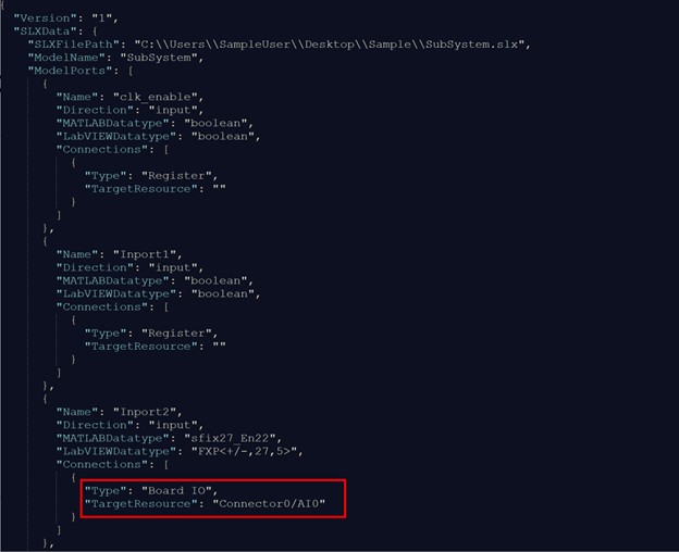
Before modifying the configuration file, read the file’s Board I/O details. Understanding the direction and datatype of the model port and Board I/O is essential to determining the correct connection configuration. The following is a snippet of a model port mapped to a Board I/O.
Note: Using the build-bitfile command will trigger a data loss warning if the model port bitness does not match the mapped Board I/O bitness.
Command Options | Description | Example | |
|---|---|---|---|
-v, --verbose | Increases output logging verbosity. | ||
| create-config | Creates a configuration template file for the specified NI FPGA. This file can be used to map model ports to a Board I/O.
The configuration file can be passed on as an option for the build-bitfile command
| ip2fpgaCLI.exe create-config -p "C:\Users\SampleUser\Desktop\Sample\SubSystem.slx" -t "PXIe-7867R" -l 2019 -o "C:\Users\ SampleUser\Desktop\Sample\SubSystem.JSON" | |
-p, --project=<value> | Specifies a path to a Simulink (.slx) project. Simulink must successfully generate HDL code before using this command. | ||
-t, --target=<value> | Specifies the NI FPGA target type to generate the bitfile. Enter the value as either PXIe-7867R or PXIe-7868R. | ||
-l, --lvversion=<value>(optional) | Specifies the LabVIEW version used to compile the bitfile. If not specified, the default is the latest LabVIEW version. | ||
-o, --output=<value>
| Specifies the path for saving the configuration (.json) file. | ||
build-bitfile |
| Builds a bitfile from the provided SLX file and targeting the specified NI FPGA Board.
| ip2fpgaCLI.exe build-bitfile -p "C:\Users\SampleUser\Desktop\Sample\SubSystem.slx" -t "PXIe-7867R" -l 2019 -c "C:\Users\ SampleUser \Desktop\Sample\SubSystem.JSON" |
| -p, --project=<value> | Specifies a path to a SLX file. Simulink must successfully generate HDL code before using this command. |
|
| -t, --target=<value> | Specifies the NI FPGA target type to generate the bitfile. Enter the value as either "PXIe-7867R" or "PXIe-7868R". |
|
| -l, --lvversion=<value>(optional) | Specifies the LabVIEW version used to compile the bitfile. If not specified, the default is the latest LabVIEW version. |
|
-n, --nocompile (optional) | If present, execution will stop after generating the LabVIEW FPGA project. No bitfile will be compile.
For more information on this command, refer to Advanced Modifications. | ||
-c, --configfile=<value> (optional) | Specifies the path to a Configuration file (.json). If not specified, the default is to map model ports to board I/Os. | ||
generate-lvproj |
| Generates a LabVIEW FPGA Project (.lvproj) for the specified FPGA board from the provided Simulink model (.slx) or .nihdlwprj file | ip2fpgaCLI.exe generate-lvproj -p "C:\Users\SampleUser\Desktop\Sample\SubSystem.slx" -t "PXIe-7867R" -l 2019 -c "C:\Users\ SampleUser\Desktop\Sample\SubSystem.JSON" |
-p, --project=<value> | Specifies a path to a Simulink model (.slx) or . nihdlwprj file. As a prerequisite, Simulink must successfully generate HDL code. | ||
-t, --target=<value> | Specifies the NI FPGA target type to generate the bitfile. Select either "PXIe-7867R" or "PXIe-7868R". | ||
-l, --lvversion=<value>(optional) | Specifies the LabVIEW version used to compile the bitfile. If not specified, the default is the latest LabVIEW version. | ||
-c, --configfile=<value> (optional) | Specifies the path to an FPGA Board IO Configuration file (.JSON). | ||
compile-lvproj |
| Builds a bitfile from the provided LabVIEW FPGA project file (.lvproj). | ip2fpgaCLI.exe compile-lvproj -p "C:\Users\SampleUser\Desktop\Sample\PXIe-7867R.lvproj" -l 2019 |
| -p, --project=<value> | Specifies the path to a LabVIEW FPGA project file (.lvproj).
|
|
| -l, --lvversion=<value> (optional) | Specifies the LabVIEW version used to compile the bitfile. If not specified, the default is the latest LabVIEW version. |
|
Note: Use NI FPGA Bitfile Generation Workflow in the HDL Coder Workflow advisor to generate the .nihdlwprj file. HDL Coder Support Package for NI FPGA Hardware is required to be installed to use this workflow. Execute Generate Project step to create the .nihdlwprj file. The file will be found in hdl_prj\ip2fpgacli
LabVIEW users may want to make the following changes:
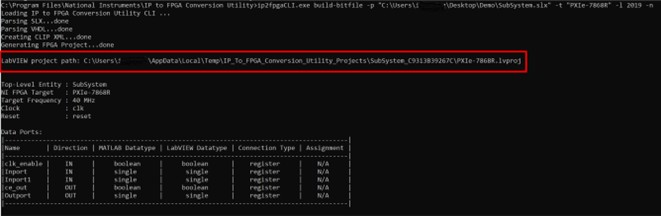
To do so, open the LabVIEW project generated by the build-bitfile command using the command option -n:
ip2fpgaCLI.exe build-bitfile -p "C:\Users\SampleUser\Desktop\Sample\SubSystem.slx" -t "PXIe-7868R" -l 2019 -n
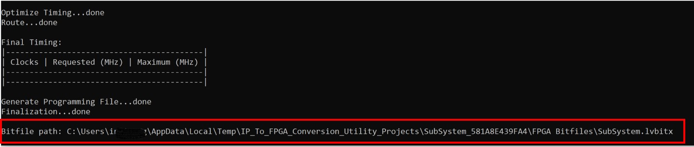
Use the generated LabVIEW project file to make the necessary modifications. You can find this file at the path displayed in the output window.