General Modbus Information
The Modbus communications protocol is a widely-used serial communications standard for many Programmable Logic Controllers (PLCs) and other industrial control devices. Modbus can function in full-duplex RS232 mode or half-duplex RS485 mode, as well as newer implementation variants such as TCP/IP. The communication is master-slave / server-client driven.
When using serial, you can set up controllers to communicate on standard Modbus networks using either of two transmission modes: ASCII or RTU. Users select the desired mode, along with the serial port communication parameters (baud rate, parity mode, etc) during configuration of each controller. The mode and serial parameters must be the same for all devices on a Modbus network. The selection of ASCII or RTU mode pertains only to standard Modbus networks. It defines the bit contents of message fields transmitted serially on those networks. It determines how information is packed into the message fields and decoded.
When controllers are set up to communicate on a Modbus network using ASCII (American Standard Code for Information Interchange) mode, each eight-bit byte in a message is sent as two ASCII characters. The main advantage of this mode is that it allows time intervals of up to one second to occur between characters without causing an error.
When controllers are set up to communicate on a Modbus network using RTU (Remote Terminal Unit) mode, each eight-bit byte in a message contains two four-bit hexadecimal characters. The main advantage of this mode is that its greater character density allows better data throughput than ASCII for the same baud rate. Each message must be transmitted in a continuous stream.
Modbus TCP/IP allows for devices to be configured and accessed on an Ethernet network while still using the characteristics of the Modbus protocol. So you can implement a server-client architecture and have multiple clients access the same devices simultaneously, versus the peer-to-peer or master-slave connection of RS232 or RS485.
Regardless of the type of protocol or mode you use, Lookout provides several Modbus drivers to implement the communications easily and quickly create an application. For more detailed information about the Modbus protocol, refer to the Modbus Organization web site.
See Also:
Modbus Organization
Configuration of Modbus in Lookout
When configuring Lookout for Modbus communication, you must first determine the proper driver to use with your device. The following Modbus drivers exist in Lookout:
- Modbus: You can use the Modbus and ModbusMOSCAD objects to communicate with equipment that uses the Modbus Serial (ASCII or RTU), Modbus Plus communication protocol, or Modbus Ethernet. The Modbus object is suitable for communicating with all Modbus compatible devices.
- ModbusMOSCAD: The ModbusMOSCAD object works with Motorola MOSCAD PLCs and RTUs. It also uses the Modbus Serial (ASCII or RTU) or Modbus Plus communication protocol, but its data members reflect the address of Motorola MOSCAD devices.
- ModbusOmni: Use the ModbusOmni object to communicate with the Omni 6000/Omni 3000 Flow Computers (firmware Version 70+). This driver uses the Modbus communication protocol with a few device-specific modifications.
- ModbusDaniel: Use the ModbusDaniel object to communicate with the Daniel Industries flow meter RTUs that use the Daniel Industries version of the Modbus protocol.
- ModbusSlave: The ModbusSlave object acts as a slave to equipment such as PLCs, distributed control systems (DCSs), or other devices that can act as a Modbus master. The ModbusSlave object enables Lookout to respond to unsolicited messages generated by other devices on a Modbus protocol network.
Each of these objects is based on the Modbus protocol but may be used in different situations, depending on the device with which you are communicating. For this tutorial, we will use the Modbus driver for communication.
Configuring the Driver
- Launch Lookout and create a new process.
- Open the Select Object dialog box by selecting Object»Create.
- Double-click on the Drivers folder, select the Modbus object, and click OK.
- Click OK on the Select Location for New Object dialog to place the Modbus object into the current process.
The Create Modbus Secondary dialog box appears, which contains all of the parameters associated with configuring Modbus communication.
The main parameter of this dialog window is the Mode, which allows you to specify Modbus serial, Modbus Plus, or Modbus Ethernet communications. If Modbus Serial is selected, all serial port settings are listed for configuration. If Modbus Plus is selected, only the address of the device on the network must be specified. If Modbus Ethernet is selected, the IP address of the device and the Identifier, if any, must be specified.
Note: To ensure that you properly configure this driver, you should understand the configuration of the device with which you will be communicating.
For more information on the three different modes, as well as the other parameters listed in this dialog box, refer to the Lookout Help.
- After you enter the necessary parameters, click OK.
Remote Access to a Modbus Device
- Launch Object Explorer by selecting Object»Object Explorer.
- Expand your current process and expand the Modbus object to display all data members.
For testing purposes, identify a register of your device to which you can read/write data. You will use this register for general testing before further configuration is done.
- Locate the appropriate range of registers. For example, if you want to communicate with register 40120, locate the 40001-49999 range.
- Set up read/write access to that register by right-clicking the 40001-49999 range of registers from the Object Explorer and dragging onto the control panel. This creates a remote connection to that Modbus register, and you can to read from and write to the register using a single control.
After releasing the mouse button, select Create Control»Pot.
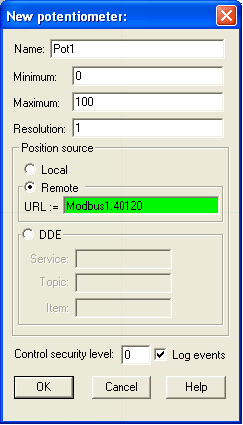
The New Potentiometer dialog box appears. Specify the minimum value, maximum value, and resolution that you want this object to contain. Make sure you modify the URL parameter to the register of interest. For example, to write a value to register 40120, change the URL to Modbus1.40120. Click OK to close the dialog box.

At this point, you can use the Potentiometer to write a value to the register on the device as well as read the current value of the register on the device.
Note: This tutorial uses a Pot object because the 40001-49999 range of registers refers to 16-bit unsigned integers ranging from 0-65535. If the register selected referred to a Boolean, a Switch or Pushbutton object would be used.
Creating a remote connection to a Modbus register allows a single-point connection to read and write a register. These remote connections are the best way to communicate between a Lookout process and a Modbus device.
To learn about other methods of accessing Modbus data members, refer to the related tutorial on "Accessing Lookout Driver Object Data Members", linked at the bottom of this section.
Configuring Connections, Alarms, and Datalogging
After you test basic reading and writing and verify communication with the device, you might need to configure connections between registers and objects/expressions within your Lookout process. You might want to configure alarm conditions, implement scaling, or configure registers to be logged to a historical database. The following sections list the basic steps for each configuration option.
Aliases
First, you may choose to create aliases, or descriptive names, for your registers so that they are easier to identify in Lookout.
- Within Object Explorer, right-click on the name of the Modbus driver, which in this tutorial is Modbus1, and select Edit Data Member Configuration.
- Type a descriptive name into the box labeled Alias (optional).
- Select the appropriate range of registers from the Native Members section. In this tutorial, we select the 40001-49999 range.
- In the Member field enter the register to which the alias is assigned.
Scaling
You might need to configure scaling to convert the raw values of a register to the proper values based on what the data represents. For example, you might receive a value of 0-100 which represents the percentage output of a level probe, but the actual value should be 0-500 in centimeters.
- In the Scaling section at the bottom-left, enter the minimum and maximum raw units, 0 and 100 in this example for the raw values of the 40120 register. Also enter the minimum and maximum values of the engineering units to which you would like to scale the raw values. In this example, a level probe represents the tank level from 0-500 centimeters.
Note: This is a linear scaling method from the minimum to maximum values. If you need polynomial scaling, you can use an expression in Lookout. For more information on creating expressions, refer to the Lookout Help or the Lookout Developer’s Manual, linked at the bottom of this section.
Alarm Conditions
You might want to configure alarm conditions for your registers. In this example, you might want to configure a high-priority level alarm to alert an operator if the tank level gets too high or too low.
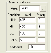
- In the Alarm Conditions section at the top-right, click the "...." button to the right of the Area text entry to browse the available alarm areas already configured for the application. You can create a new alarm area by typing a new name into the Area field. For this example, create a new alarm area called Tanks.
- Enter values for the HiHi, Hi, Lo and LoLo limits. For this example, a HiHi alarm is generated at 475, Hi at 400, Lo at 150, and LoLo at 50.
- Enter a priority level for each of the alarm limits. For this example, HiHi and LoLo are priority 9 and Hi and Lo are priority 6.
- Enter a Deadband value to be applied to all alarm limits. This value represents the amount of change that must take place before an alarm condition changes states. This deadband prevents hysteresis if a noisy signal changes rapidly around an alarm limit.

For more information about alarm areas, priority levels, or deadbands in Lookout, refer to the Lookout Developer’s Manual.
Historical Logging
You might want to configure registers to be logged to Lookout's Citadel historical database. Lookout can monitor all configured registers and log all appropriate values to a database, efficiently storing data in making it easily accessible at a later time.
- Check the Log to historical database checkbox and choose an appropriate Lifespan. Lookout needs to know how long you want to maintain this trace of data in Citadel. Lookout maintains the data for the time span specified in this field. For this example, 7 days of data is logged, then the oldest data is overwritten.
- Enter a value in the Deviation field. If a change in a numeric value surpasses or equals the deviation setting, Lookout logs a new value to Citadel. If you implement scaling parameters, Lookout compares the deviation setting to changes in the engineering units values to determine when to log a new value. If you leave the scaling blank, Lookout compares the deviation setting to the raw value.
Note: Careful consider your deviation setting. If you do not specify a deviation, any change in a numeric value results in a new value being logged to disk, and you might log more data than you need. If the deviation setting is too large, very little information might be saved to disk.
For more information on historical logging, refer to the Lookout Developer’s Manual.
- Click the Save/Update button to save all changes.
The final configuration should appear as follows:
Note: The description and suffix are used for descriptive purposes only and do not affect functionality.
- Repeat as necessary to set up different registers. When you are done, click the Quit button to exit the dialog.
Connections to Objects and Expressions
You need to make connections between the alias, or registers, and other objects/expressions of your Lookout process.
First, create a new potentiometer to connect to a Modbus register.
- Open the Select Object dialog box by selecting Object»Create.
- Double-click the Control folder, select the Pot object and click OK.
- Click OK in the Select Location for New Object dialog box to place the Pot object into the current process.
The New Potentiometer dialog box appears, which contains all of the parameters associated with configuring the Pot object. The name of the new potentiometer should be Pot2.
- Click OK to add the object to the process.
- Within Object Explorer, right-click on the name of the Modbus driver and select Edit Connections.
- In the Writable Members section in the top-right corner, highlight the alias or range of registers to which you want to make a connection. The selected entry is displayed just below in a text indicator. For this example, select the 40001-49999 range of registers. The default displayed is 40001.
- After specifying the alias or register, click the Select button to make it the current connection.
- In the Signals area at the bottom, expand your process and highlight an object that you would like to connect to the alias or register selected in the previous step, then select the specific data member. In this example, the 40001 register is selected and a connection is made with Pot2.value.
In the middle of the dialog window you will notice the expression which states the connection being made. In this example, the expression is Modbus1.40001 = Pot2.value.
Note: It is very important to understand the expression shown because these connections are unidirectional. Modbus1.40001 is equal to Pot2 and will change anytime Pot2 changes; but Pot2 will never change to coincide with 40001 if that value is changed elsewhere.
For more information on connections, refer to the Lookout Developer’s Manual.
- Click the Accept button to save the connection.
- Repeat as necessary to create connections between objects and aliases or registers. When you are done, click the Quit button to exit the dialog.
Displaying Historical Trends
After you set up and configure all Modbus registers in your process, you might want to monitor the data in a historical trend view on your panel. This will allow you to view the data as it is being logged to the database and also view all historical data.
- Open the Select Object dialog box by selecting Object»Create.
- Double-click on the Display folder, select the HyperTrend object, and click OK.
- Click OK on the Select Location for New Object dialog box to place the object into the current process.
The Create HyperTrend dialog box appears, which contains all of the configuration options associated with the HyperTrend object.
- Click the Add Group button to create a group for the HyperTrend.
- In the Add Group dialog box, enter a name for your group. In this example, create a group called Tanks. This takes you back to the Create HyperTrend dialog.
- Click the Add Item button to select aliases or registers to view.
- Right-click in the green area of the URL to bring up the URL Editor dialog window.
- In the URL editor, browse to the Modbus object and select the alias, or register, that you would like to view on the HyperTrend. In this example, we will view the Tank_Level.
- Because the Tank_Level is being scaled to 0-500 cm, we will adjust the scale of the HyperTrend to accommodate this range. In the Add Item dialog, change the minimum and maximum values to 0 and 500 respectively.
- Click OK to return the Create HyperTrend dialog.
Note: At this point, the HyperTrend will display the Tank_Level alias. An alias or register must be logged to the historical database in order to be viewed on the HyperTrend.
- Click OK to save the configuration of the HyperTrend object.
- In Object Explorer, left-click the hypertrend1 object and drag it to the panel. Resize as necessary.
In this example, the Tank_Level alias is displayed on the HyperTrend. Any changes to that alias, or to the Pot that contains a remote connection to the alias, is displayed.
If for some reason you do not see your data being displayed, reference the following KnowledgeBase linked below which may address the issue. For more information on the HyperTrend, refer to the Lookout Developer’s Manual.
See Also:
Lookout Developer's Manual
Basic Troubleshooting Options
After configuring Lookout to communicate with your device, there may be times when you need to monitor or troubleshoot the communications. Lookout includes tools to help you investigate performance or unexpected behavior with Modbus communication.
Modbus Protocol Statistics
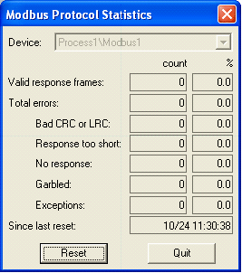
The Modbus driver monitors Modbus Protocol Statistics. This data is held within readable data members of the Modbus object and you can see them in the Modbus Protocol Statistics dialog box. To view the dialog box, select Option»Modbus and click Statistics.
Note: The Options»Modbus option is only visible in the Options menu if a Modbus object exists in your Lookout application.
The following dialog appears.

- Valid response frames: The number of good messages received from the polled device.
- Bad CRC or LRC: Number of responses from device whose message failed the cyclic redundancy check (CRC) or the longitudinal redundancy check (LRC).
- Response too short: The number of responses from the device whose message length was too short.
- No response: The number of polls generated by the driver not responded to by the device.
- Garbled: The number of responses from the device whose message was unintelligible to the driver.
- Exceptions: The number of responses from the device whose message was understandable to the driver but included an error code indication from the device.
The Count column contains the accumulated number of messages received from the selected device that fall into each respective category since the last time the Reset button was clicked. The percent column (%) indicates the percentage of messages received that fall into each respective category since the last time the Reset button was clicked.
Refer to the Lookout support page and tutorial linked at the end of this section for more information on troubleshooting related issues.
Alarms Window
After you have created a Modbus object and attempted to make a connection, any issue that occurs with the communications generates an alarm for that driver. The alarm information often coincides with data seen in the Protocol Statistics dialog.
Refer to the Lookout support page linked at the end of this section for the most common alarms and an explanation of the potential causes.
Monitoring Modbus Communications
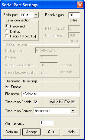
If you have received alarms related to garbled communication or any other of the protocol statistics, you might want to view the actual serial data sent to and from the device. To record this serial communication, configure Lookout to log the data to file by selecting Options»Serial Ports and enabling the diagnostic file settings. Also check the options for Timestamp Enable and Value in HEX to make the file more readable and useful for troubleshooting.

Note: Make sure that you are configuring the proper serial port for the Modbus device.
If you are communicating with a device via Modbus Ethernet, refer to the KnowledgeBase linked at the end of this section for information on logging the communications.
The example below shows Modbus data captured on the serial port. By analyzing this data and comparing it to the protocol format and the data that the device should be sending/receiving, you can troubleshoot where an issue may be occurring. For more information on the Modbus protocol and how to interpret the data, refer to the Modbus Organization web site link at the end of this section.

From the sample shown above, you will notice that the first message was generated at 15:44:24.5 (3:44pm, 24.5s). The arrow pointing to the right denotes that the communications is TO the device. If a response is received FROM the device, the arrow points left. First, the message is sent in RTU format; the default. Because the device did not respond, the message was sent in ASCII format. There is still no response from the device therefore the message continues to repeat while a “No Response from Modbus Secondary” alarm is generated.
Modbus Slave
There may be times when you are developing a Lookout application, but you do not have access to the device to which the Modbus driver will communicate. In this case, you might want to simulate the device so that the application can be tested. In this situation, a Modbus slave object can be used to simulate the device.
In order to simulate the device, configure the ModbusSlave object and set up the local computer as follows:
1. Connect a NULL serial cable between two COM ports on your computer.
2. Create a ModbusSlave object in Lookout for one of your COM ports.
3. Create a Modbus object for your other COM port with matching baud rate settings.
Note: The ModbusSlave can also be set up and accessed from another computer. The other computer would also need a server version of Lookout to accomplish this configuration.
Advanced Settings
In certain situations, you might need to apply more advanced settings to your Modbus communications for proper and efficient functionality. You can access advanced Modbus options from the Create Modbus Secondary dialog.
For more detailed information on the advanced settings, refer to the Lookout Help.
See Also:
For more information on Modbus communications in Lookout, refer to the Lookout Help, the Lookout Developer’s Manual, and the Lookout support web page.