Integrate a UPS into the NI ECU Test System
Overview
This document will walk you through the process of integrating an Uninterruptible Power Supply (UPS) into your NI ECU Test System (ECUTS).
Contents
Benefits of a UPS
By integrating a UPS into the ECUTS, you can preserve some system functionality in the event of loss of facility power to the system. The UPS can keep some internal ECUTS components powered on for a limited time without incoming facility power. The amount of uptime granted by a UPS depends on the power consumption of the reliant components and the size of the battery in the UPS. The limited extra uptime attained with proper UPS integration may allow for a functional shutdown of ECUTS without damage to components or loss of data if facility power is interrupted.
NI does not ship or support UPS products in the ECUTS, nor modifications required to integrate one. Follow the recommendations in this document to integrate a UPS to your ECUTS if you require this functionality, and comply with all safety, environmental and regulatory requirements for the ECUTS and your UPS.
Choosing a UPS
Ensure you choose a UPS that accepts the appropriate input voltage. The internal AC power system of the ECUTS will match the system input voltage. Consult the system input voltage in the system’s specifications sheet. Ensure the UPS is also compatible with your facility power.
Also note that UPS products have limited power output. Integrating a UPS into the ECUTS may limit the power budget for equipment within the system. Ensure that the UPS does not dissipate more power than is allowed in an ECUTS system with consideration of intake and exhaust temperatures and airflow to not exceed maximum internal rise temperatures within the ECUTS rack enclosure. You can consult these specifications your system’s User Manual.
Configuring the UPS inside the ECUTS rack will also consume space that may normally be configured with other equipment. Ensure that there is sufficient room to place a UPS within your ECUTS as configured.
Make sure that the UPS to be configured is certified and in compliance with regulatory requirements in the region of use. Additionally, the UPS must be appropriately rated and installed according to installation instructions of the UPS manufacturer. If configured internally into the ECUTS, it must be rated to tolerate the internal temperatures of the ECUTS rack.
ECUTS Power System
Block Diagram

The Emergency Power Off (EPO) panel can inhibit the output of the Power Entry Panel (PEP) and Power Distribution Unit (PDU). Small arrows indicate inhibit connections, while large arrows indicate the flow of power.
System Schematic
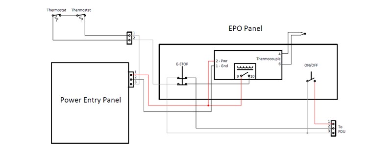
The above figure shows the system power inhibit signal wiring in ECUTS as configured by NI. NI does not support modification of this circuitry. However, additional circuits can be added to control the state of a UPS, and it is possible to use the existing emergency stop (E-STOP) and on-off switch in additional circuits. Refer to the Integration Components section of this document for more information.
Behavior
The following describes the behavior of the ECUTS power system under various conditions and states. This table assumes that the main breaker, secondary breakers on the PEP, if applicable, and PDU breakers are all in the On position. The Facility Power column is meant to reflect the power state on the outside of the PEP – if there is AC power to the PEP, the system will behave as if facility power is present whether that power comes from a facility UPS or directly from facility power. Refer to the user manual of your system for more details on these states.
Facility Power* | Main Breaker | Power Switch | EPO | Temperature Controller Relay | PDU Output | PEP AC output | Power State |
|---|---|---|---|---|---|---|---|
On | On | On | On | On | Enabled | Enabled | On |
On | On | Off | On | On | Disabled | Enabled | Standby |
On | On | On/Off | Off | On | Disabled | Disabled | EPO |
On | On | On/Off | On/Off | Off | Disabled | Disabled | EPO |
Off | On | On | On | On | Disabled | Disabled | Power Loss |
On/Off | Off | On/Off | On/Off | On/Off | Disabled | Disabled | Off |
- On—A change to this state begins the ECUTS main power sequence. All PDUs receive AC power and enable outlets to other instruments.
- Off—The ECUTS is entirely disabled with no power passing through the line filter or any internal test rack components.
- Standby—AC and DC power is passing out of the PEP and into the temperature controller on the emergency power off (EPO) panel and the PDU. Neither AC nor DC power are passing out of the PDU.
- Emergency Power Off (EPO)—Pressing the EPO button immediately disables AC output from the PEP and AC and DC outputs from the PDU. This state is non-latching – if the temperature controller or EPO button once again enter their ‘on’ states, the system will turn on if all other requirements for the On state are met.
- ECUTS has safety shutoff thermostats which, when tripped, will latch the system into EPO state until they are manually reset. These thermostats trip when a dangerous over-temperature is detected in the exhaust of the system.
- Power Loss—Facility power is absent. Loss of facility power will automatically disable the outputs from the PEP and PDU, even if a UPS is configured in the system and supplying AC power to the PDU. If the PEP does not have AC input, the PDU output will be disabled.
The table describes only when PEP or PDU outputs are enabled or disabled. Note that when AC power is not present at the PEP input, output from both PEP and PDU is inhibited – so even if a UPS provides power to the PDU from within ECUTS, it will not be able to power devices plugged into that PDU.
In most cases, it is important to make sure the system controller is protected by the UPS. In the event of an overheat, EPO event, or power off, the PDU output will be inhibited. In order to behave as desired, the UPS output must not be inhibited in the event of power loss.
The system exhaust fans are powered by the DC output of the PDU. If this PDU is not protected by the UPS, the system fans will power down while the UPS continues to provide power to connected instruments. This can lead to unexpected high temperatures within the system if it is not shut down promptly. Take care to ensure your system will not become thermally hazardous in this state.
Note: DUT fixtures on ECUTS are by default powered by the DC output of the PDU. Consider using an alternate source of DC power for the fixture if it is necessary to keep it powered in a Power Loss state.
Integration Components
Additional signals can be added to the existing power switch and EPO button on ECUTS by using add-on modules designed for the purpose. NI recommends IDEC TW 22mm Metal Bezel Series components.
- The ECUTS power selector switch is IDEC part number ASW210.
- The ECUTS EPO button is IDEC part number AVW402-R.