Satellite Communication Bus Interface Selection
Overview
Communication bus, or digital avionics, interfaces are a necessary component of functional test systems for satellites and launch vehicles—but choosing the right instrumentation isn’t always straightforward. While some standard interface buses can be addressed by commercial-off-the-shelf (COTS) devices, others have unique requirements or are too niche for a dedicated instrument. NI, and the community of PXI instrumentation vendors, can meet the needs of common, uncommon, and even custom interfaces with a range of product options. This paper discusses the underlying technical requirements of testing a communication bus and the merits of choosing a modular system approach.
Contents
- Introduction
- Selecting the Best Bus Interface Instrument
- NI’s Role in Satellite Communication Bus Interfaces
- When Custom Design is a Hard Requirement
Introduction
Test engineers can generally agree on the importance of the adage “pick the right tool for the job.” That’s because using the wrong tool can waste time and compromise quality, whereas the right tool can deliver the correct result in a fraction of the time.
The primary tools come in the form of measurement and stimulus instrumentation when building electronic ground support equipment (EGSE) or specialty checkout STEs (SCOS, with STE standing for specialty test equipment) for integration, checkout, and high-volume manufacturing test. These instruments include known commodities like digital multimeters (DMMs), oscilloscopes, and waveform generators as well as a variety of new and changing categories of products like vector signal transceivers and all-in-one oscilloscopes. But picking the right tool for the job is much easier said than done, especially when it comes to navigating and evaluating the many trade-offs at play. This applies to commoditized and specialty instruments alike; however, satellite communication bus interfaces often are not considered with the same level of rigor.
When considering the list of instrumentation that should go into the EGSE used for validation or integration test, test engineers are accustomed to consulting their test plans and evaluating the instrumentation on the market to ensure the right instruments are installed to provide full measurement coverage to satisfy the test plan requirements.
Often, the test plan for a particular device under test (DUT) requires additional steps to put the DUT into a particular state or send it a command and listen for the expected response; this is especially true when testing flight and system controllers. These steps might include running quality assurance checks, running a subset of the design verification steps on the avionics bus itself, or recording responses for later analysis or playback. To ensure this functionality is built into the EGSE, test engineers often look to which protocol(s) the DUT uses for communication as well as the commercial off-the-shelf (COTS) market for an instrument to fit their needs.
Selecting the Best Bus Interface Instrument
Depending on the combination of test asset platform and the specific DUT, there are a wide range of options for a particular avionics bus interface instrument to choose from. When considering the most common protocols such as MIL-STD-1553, ARINC-429, and SpaceWire, there are several instrument providers on the market that have off-the-shelf options that can meet those needs. However, when considering high-speed or backbone buses like Fibre Channel (specifically SpaceFibre), Serial RapidIO (SRIO), AFDX, High-Speed Data Bus (HSDB), and IEEE-1394b—or application-specific buses like ARINC-708, ARINC-717, or ARINC-818—the options become much more complex and involve more considerations.
Many bus interfaces, like SpaceWire, have become so prevalent that the interface instruments have become commoditized. It has become more cost effective for test equipment vendors to integrate the physical, data link, and network layers into a fixed-function device. For example, STAR-Dundee offers multiple PXI modules for interfacing and switching SpaceWire bus signals. Like instruments for other broadly adopted communications protocols—such as GPIB—at the hardware levels, these instruments are often architected similarly from vendor to vendor to comply with the specific standard.
Where a test equipment vendor might differentiate their product over another comes in the higher data layers of the Open Systems Interconnection (OSI) model where specific features or capabilities to support the protocol are implemented. These include error detection, scheduling flexibility, timestamping, data recording, and fault insertion—just to name a few. Some manufacturers also provide access to the data at each individual OSI layer for monitoring or debugging. For system-level validation and integration test requirements, many of the more nuanced features often are not as critical to application success, so the decision typically falls to the engineer’s preference.
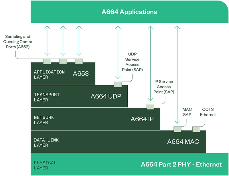
Figure 1. Simplified View of the OSI Layers of ARINC-664p7/AFDX
When a test system requires high-speed/backbone or application-specific protocol interfaces, a once-simple selection decision becomes much more challenging. Test engineers often overlook the complexity associated with integrating these protocols into their test systems. One of the major challenges introduced with these higher-performance protocols is the move from parallel to serial data transmission.
Serial standards have been gaining in popularity because the physical limitation on the clock rates of parallel buses is around 1 GHz to 2 GHz; skew introduced by individual clock and data lines can cause bit errors at faster rates. Instead, high-speed serial buses send encoded information that contains both data and clocking information in one or more differential signals, avoiding the speed limitations with parallel buses. Furthermore, using specialized high-speed serial hardware transceivers with advanced capabilities like clock recovery, pre-emphasis, and equalization push these advantages even further.
Designs for high-speed serial protocol interfaces lend themselves nicely to running on the latest FPGA technology. For example, the multi-gigabit transceivers on the latest Xilinx FPGAs can operate faster than 30 Gb/s, making them ideal candidates to act as the data processor for a communication protocol. In addition to the complexity of the hardware design for these instruments, the protocol IP itself is also more complex than a commodity instrument since the protocols tend to be much more full-featured and have more stringent data requirements due to the complexity required to handle the order of magnitude increase in data rates.
When it comes to integrating a particular high-speed/backbone or application-specific protocol interface into an EGSE, engineers are often faced with a couple of options.
- Option 1 is to look to the COTS market and find a vendor that offers the interface in question. Again, due to the complexity of the hardware design and the IP, engineers must often work with two vendors—one for the high-speed serial hardware, and one for the protocol IP core.
- Option 2 is to leverage the design from the internal validation team for the DUT in question which combines an IP core with either a custom or off-the-shelf FPGA evaluation board and integrate it into the EGSE. While leveraging an in-house custom design may seem attractive, there are often unseen risks that can substantially increase the support burden over time.
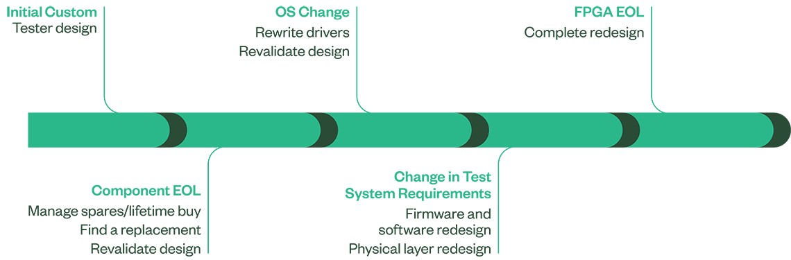
Figure 2. Life-Cycle Management of a “Homegrown” Test System
To illustrate this, Figure 2 depicts an example over the lifespan of a test system and the events impacting maintenance costs of that system over time. After the EGSE is fully designed, consider that a component on your custom board goes end-of-life (EOL). This is to be expected after all, as semiconductor technology refresh cycles tend to reflect the commercial market. And it is especially likely if a design is adopted from the validation team since life-cycle concerns were likely not included in their design requirements.
In a situation like this, either a lifetime buy of that component and managing spares or finding a replacement and revalidating the hardware design are essentially the only choices. Or consider a mandate for an OS upgrade such as a Windows version change—or perhaps a move to Linux. Then, drivers must be rewritten and the software design revalidated. What if requirements for the tester change over time, or new features need to be added? This could require a redesign for firmware or software—or even possibly the physical layer, depending on DUT requirements. And finally, what about when the FPGA goes EOL? There isn’t an easy upgrade path for these components, so a complete redesign is often required.
These are very realistic occurrences for a test system that, in the aerospace and defense industry, likely will need to last for decades. Many times, when these obsolescence challenges occur, the people who designed the original EGSE and the test software programs that run on them are no longer around to assist with any maintenance efforts. Ultimately, the upfront design cost is only a very small percentage of cost of the test system over its lifetime
Instead, whenever possible, engineers should consider Option 1: a COTS-based solution, specifically one designed to be used in test and measurement applications. Even with in-house capability to design and manage the complex software IP required to interface with the satellite communication protocol, the additional maintenance and sustainment burden of the custom hardware means that a COTS approach will reduce the total cost of test.
NI’s Role in Satellite Communication Bus Interfaces
For decades, the aerospace and defense industry has used NI’s modular instrumentation and application software to reduce the overall cost and risk associated with the test and support of its products. During that time, NI pioneered the PXI platform, and since has released more than 600 different PXI modules ranging from DC to mmWave. In addition to traditional instrumentation, the integration, checkout, and high-volume manufacturing test solutions provided both by NI, our network of partners, and the 70+ members of the PXISA providing PXI platform elements, like like STAR-Dundee, offer the most comprehensive coverage of PXI-based bus interfaces while maintaining the flexibility to choose the “right tool for the job.”
Digital Avionics Interfaces for Manufacturing and Depot Test
Generic Interfaces:
- MIL-STD-1553
- RS-232/422/485
- ARINC-429
- CANbus
High-Speed/Backbone Interfaces:
- Fibre Channel (specifically SpaceFibre)
- Serial RapidIO
- ARINC-664p7/AFDX
- 1394b FireWire
- Ethernet (Up to 40 GigE)
Application-Specific Interfaces:
- ARINC-708
- ARINC-717
- ARINC-818
- SpaceWire
- DVI
When Custom Design is a Hard Requirement
There are instances when a test engineer may believe a COTS approach is not viable and custom engineering is required. An often-cited example is testing a DUT that communicates over a customized version of a particular protocol. Nevertheless, even in these cases avoiding custom design is recommended to reduce the schedule risk and future maintenance burden of the test EGSE. To learn more about building full electronics test systems for space, including integrating COTS communication bus interface hardware into your test systems to solve custom design challenges, read the application note.