NI does not actively maintain this document.
This content provides support for older products and technology, so you may notice outdated links or obsolete information about operating systems or other relevant products.
Imagine that you want to measure the temperature of a chamber with an electrical thermometer. You might want to apply heat and then immediately measure the temperature. In this case, you would start, or trigger, the acquisition as soon as the heat is applied. A trigger is an event, such as the completion of heat being applied in this example, that causes or starts an acquisition. Triggering requires that certain conditions be met before data is acquired. Once the triggering conditions are met, the acquisition begins immediately and continues until all requested data is gathered or a user stops the acquisition.
You also can configure a pretriggered acquisition, so the hardware starts acquiring data before the trigger signal is received, enabling you to look at the signal before the trigger event. In a pretriggered acquisition application, the hardware initiates data acquisition with a software function and stores the data in a circular buffer in PC memory. The size of this buffer is large enough to ensure that the required number of pretrigger samples is stored. When the buffer is full, it wraps around and stores each subsequent sample over the oldest sample in memory. The primary responsibility of the trigger mechanism is to stop the acquisition at the right time so that the sampled information left in memory represents what the user needs to view. The trigger signal in this case is also referred to as the stop trigger.
Consider the same chamber, but apply continuous heat. Now you want to acquire data every time the chamber reaches a critical temperature. For this type of acquisition, you would monitor the chamber temperature and collect data every time the temperature exceeds the critical temperature, say 500°. This critical temperature is the gating condition. A gate is an external signal that pauses and resumes acquisition based on some condition, such as the chamber temperature exceeding 500°. With gating you can pause and resume acquisition based on the configured conditions.
Trigger signals can originate from three different sources -- hardware digital signals, hardware analog signals, or software signals. Gate signals can originate from hardware digital signals or hardware analog signals.
Note: Check your device documentation to determine which trigger and/or gate capabilities are implemented.
Hardware Digital Signal Triggering and Gating
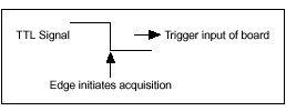
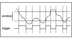
A digital signal is usually a transistor-transistor logic (TTL) level signal having two discrete levels -- a high level and a low level. When the signal switches between levels, a digital edge is created, as shown in Figure 1. You can trigger your analog acquisition on the rising or falling edge of your digital trigger signal. A rising edge occurs when the signal changes from low to high. A falling edge occurs when the signal changes from high to low. In Figure 1, the acquisition begins after the falling edge of the digital trigger signal.
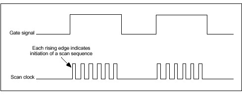
Digital gate signals are characterized by a level, rather than a digital edge, so you can configure a digital gate that pauses an acquisition while the gate signal is either in the high state or the low state. In Figure 2, the scan clock is enabled when the gate signal is high, which means that data is being acquired.
Note: Make sure your National Instruments DAQ board can perform scan clock gating. The scan clock controls the time interval between scans and gates the channel clock on and off.
Hardware Analog Signal Triggering and Gating
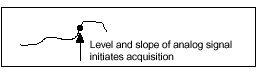
An analog trigger occurs at a selected point on an incoming analog signal, which represents a measurement that can be continuously observed and represented. You can set triggering to occur at a specific level on either an increasing or decreasing signal (positive or negative slope); that is, you specify a threshold level that the signal must cross and whether the signal is rising or falling before the acquisition begins. Figure 3 shows the point -- defined by a level and slope -- that triggers the acquisition.
Note: Make sure your National Instruments DAQ board is equipped with Analog Trigger Circuitry (ATC), which monitors the analog trigger channel. Once the conditions are met, the ATC generates an internal signal to trigger or gate the acquisition.
Analog signals are susceptible to noise, and noise can lead to premature or late triggering. To prevent incorrect triggering, you can specify a window through which the signal must pass before the trigger or gate signal occurs. Hysteresis defines the range of this window. If you wanted to set the trigger conditions for the acquisition shown in Figure 4, you would set level and hysteresis. For example, you might set level to 3.0 V and hysteresis to 0.05 V because you know that the average noise in the system is at least 0.01 V. In this example, level - hysteresis is 2.95 V.
Note: If you configured named channels in National Instruments Measurement & Automation Explorer, the signal level is relative to the physical units specified for the channel. For example, if you configure a channel called Temperature to have a physical unit of Deg. C, the value you specify for the trigger signal level is relative to Deg. C. If you are not using named channels, the signal level is volts.
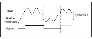
Figure 4 shows a series of situations where data is acquired when the signal exceeds level and the triggering or gating conditions are met. In this rising-edge triggered application, the acquisition begins when the signal passes through the hysteresis window and exceeds level (3.0 V). The acquisition continues until all requested scans are acquired or the acquisition is explicitly stopped. In a gated system, data acquisition is initiated when the signal passes through the hysteresis window and exceeds level. The acquisition continues as long as the signal remains above level - hysteresis (2.95 V). If the signal drops below level - hysteresis, the acquisition pauses and resumes only when the signal exceeds level (3.0 V) again.
In a falling-edge triggered application, the acquisition begins when the signal falls below the hysteresis window defined by level + hysteresis (3.05 V) and level (3.0 V), and the acquisition continues until all requested scans are acquired or the acquisition is explicitly stopped. A falling-edge gate is initiated when the signal falls through the hysteresis window and below level (3.0 V). The acquisition continues as long as the signal remains below level + hysteresis (3.05 V). If the signal rises above level + hysteresis, the acquisition pauses and resumes only when the signal falls below level (3.0 V) again.
If the value of a signal is more important than the slope, you can configure an analog trigger to occur if the signal enters or leaves a window of values, which is useful for detecting and recording fluctuations from the expected signal range. In Figure 5, two values specify the boundary of the window, where the bottom of the window is level and the top of the window is level + hysteresis. In this example, the trigger occurs the first time the signal appears inside the window, and data is acquired until all requested scans have been acquired or the acquisition is explicitly stopped. In a gated acquisition, data is acquired when the signal appears in the window.
Tip: Alternatively, you can configure the gate to occur when the signal falls below level - hysteresis or when the signal leaves the window.
Software Analog Signal Triggering
With software triggering, or conditional retrieval, you can simulate an analog trigger using software if your DAQ device does not have ATC. In a conditional retrieval application, you configure your DAQ device, set your triggering conditions, and start collecting data. The Traditional NI-DAQ (Legacy) driver scans the data and compares it with your conditions. When the data meets your conditions, Traditional NI-DAQ (Legacy) returns the data and continues acquiring the data until all requested scans have been acquired or the acquisition is explicitly stopped.
As with hardware analog triggering, you specify the level and hysteresis of the signal. You also can configure software triggers for both rising and falling slopes.
You can configure triggering and gating conditions for the Analog Input (CWAI) and Analog Output (CWAO) controls in a Condition object. The Condition object contains information about starting, stopping, or pausing an acquisition, and you configure Condition objects interactively in the property pages or programmatically through code. Measurement Studio offers the following Condition objects:
As you write your DAQ program, consider your application and whether you need to implement a trigger or gate to control the acquisition. Then decide which Condition objects you need to configure. Finally, select the overall operation of the object, which you can set next to the Condition object in the property pages or with the Type property programmatically. For example, you can specify the type of condition to use, such as none, hardware digital trigger, or hardware analog trigger. The Type property also determines which additional properties you need to set.
Tip: Refer to Configuring Condition Objects for Analog Input Operations and Configuring StartCondition Objects for Analog Output Operations later in this application note for a description of the properties you need to set for each Type property.
Starting an Acquisition or Generation with StartCondition
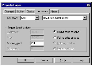
The StartCondition defines when a data acquisition or generation starts. By default the acquisition or generation begins immediately after the CWAI.Start or CWAO.Start method call. You can set the type of the StartCondition to hardware digital trigger or hardware analog trigger. Although the hardware is set to start on the Start method call, the actual analog-to-digital conversions do not begin until the digital or analog trigger fires. For example, the StartCondition object in Figure 6 defines a hardware digital trigger as a rising edge on PFI0.
Tip: Set the condition type to None to reset a Condition object to its default state.
Stopping an Acquisition with StopCondition
The StopCondition object defines when an acquisition is stopped. You can define the following triggers on a StopCondition:
The default mode stops after the acquisition buffer, set by the NScans property on the CWAI control, has been filled once. You also can select to run a continuous acquisition so the acquisition stops only on a user command. Other advanced options include stopping after a hardware digital or analog signal and stopping after a software analog condition (single-shot or continuous).
With the analog or digital trigger types, you also can configure a pretriggered acquisition so that you can retrieve and analyze a portion of the data sampled before the trigger occurred. The Pretrigger scans property specifies the number of scans that occur before the trigger to return. For example, if you want to acquire 200 pretrigger scans and 800 posttrigger scans, set CWAI.NScans to 1000 and the Pretrigger scans property to 200.
Note: The Pretrigger scans property only is available on the StopCondition.
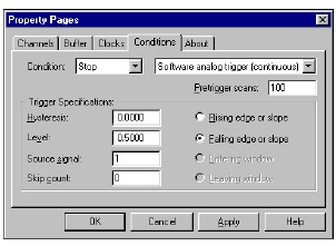
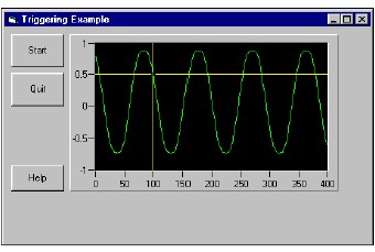
The software analog trigger type on the StopCondition provides analog triggering on devices that do not have analog trigger circuitry. In this mode, data is continuously acquired from the data acquisition device but returned only when it matches the specified conditions. This mode behaves like a hardware analog start trigger, and you can run it either as a one-shot or continuous acquisition. Figure 7 shows how you might configure a continuous software analog trigger to simulate an oscilloscope, as shown by the application in Figure 8.
Notice that the 100th sample in Figure 8 occurs at a level of 0.5 V on a falling slope, which is actually the point that the acquisition begins. Although the trigger specifications set in the property pages are met earlier in the acquisition, the data is ignored until at least 100 samples are acquired, as specified by the Pretrigger scans property.
Pausing an Acquisition with PauseCondition
The CWAI control never pauses during an acquisition by default. The PauseCondition object controls when an ongoing acquisition is paused, which might be done in response to an external digital or analog gate signal.
Configuring Condition Objects for Analog Input Operations
The following tables list the Condition objects and properties that you need to set for each trigger or gate type.
Note: Certain condition types are supported only by specific hardware. Check your hardware manual to determine if it supports the condition and operation you are trying to perform. For example, all hardware analog conditions require specific analog trigger circuitry on the acquisition device.
Hardware Digital Trigger
|
Property
|
Valid Property Page Value
|
Valid Programmatic Value
|
| Condition | Start or Stop | |
| Type | Hardware digital trigger | CWAI1.StopCondition.Type = cwaiHWDigital |
| Source | Source signal for the trigger. Leave this property blank to use the default trigger pin. For E Series devices, the default trigger source for a StartCondition is PFI0, and the default trigger source for a StopCondition is the PFI1 pin. The trigger can be set to any valid PFI or RTSI line. You can use GPCTR0 as a trigger for StartCondition. | CWAI1.StartCondition.Source = "GPCTR0" CWAI1.StopCondition.Source = "PFI0" |
| Mode | Rising edge or slope Falling edge or slope | CWAI1.StopCondition.Mode = cwaiRising CWAI1.StopCondition.Mode = cwaiFalling |
| Pretrigger Scans | Number of scans occurring before the trigger to return. Must be greater than 1 for StopCondition. | CWAI1.StopCondition.PreTriggerScans = 200 |
Hardware Analog Trigger
|
Property
|
Valid Property Page Value
|
Valid Programmatic Value
|
| Condition | Start or Stop | |
| Type | Hardware analog trigger | CWAI1.StartCondition.Type = cwaiHWAnalog |
| Source | Source signal for the trigger. Set this property to any valid analog input channel or PFI0 (E Series boards only). | CWAI1.StartCondition.Source = "1" |
| Mode | Rising edge or slope Falling edge or slope Entering window Leaving window | CWAI1.StartCondition.Mode = cwaiRising CWAI1.StartCondition.Mode = cwaiFalling CWAI1.StartCondition.Mode = cwaiEntering CWAI1.StartCondition.Mode = cwaiLeaving |
| Level | Voltage at which the analog trigger is to occur. | CWAI1.StartCondition.Level = 1.0 |
| Hysteresis | Range the signal must pass through before the trigger occurs. Default value is 0. | CWAI1.StartCondition.Hysteresis = 0.5 |
| Pretrigger Scans | Number of scans occurring before the trigger to return. Must be greater than 1 for a StopCondition. | CWAI1.StopCondition.PreTriggerScans = 200 |
Software Analog Trigger
|
Property
|
Valid Property Page Value
|
Valid Programmatic Value
|
| Condition | Stop | |
| Type | Software analog trigger (one shot) Software analog trigger (continuous) | CWAI1.StopCondition.Type = cwaiSoftwareAnalogOneShot CWAI1.StopCondition.Type = cwaiSWAnalog |
| Source | Source signal for the trigger. Set this property to any valid analog input channel. | CWAI1.StopCondition.Source = "1" |
| Mode | Rising edge or slope Falling edge or slope | CWAI1.StopCondition.Mode = cwaiRising CWAI1.StopCondition.Mode = cwaiFalling |
| Level | Voltage at which the analog trigger is to occur. | CWAI1.StopCondition.Level = 1.0 |
| Hysteresis | Range the signal must pass through before the trigger occurs. Default value is 0. | CWAI1.StopCondition.Hysteresis = 0.5 |
| Pretrigger Scans | Number of scans occurring before the trigger to return. | CWAI1.StopCondition.PreTriggerScans = 200 |
| Skip Count | Number of trigger conditions to skip. After ignoring this number of trigger conditions, the CWAI control recognizes the next valid trigger condition. This property is valid only when setting the StopCondition to software analog triggering. | CWAI1.StopCondition.SkipCount = 10 |
Continuous
|
Property
|
Valid Property Page Value
|
Valid Programmatic Value
|
| Condition | Stop | |
| Type | Continuous | CWAI1.StopCondition.Type = cwaiContinuous |
| No additional properties need to be set for continuous acquisition. | ||
Hardware Digital Gate
|
Property
|
Valid Property Page Value
|
Valid Programmatic Value
|
| Condition | Pause | |
| Type | Hardware digital gate | CWAI1.PauseCondition.Type = cwaiHWDigital |
| Source | Source signal for the gate. Leave this property blank to use the default trigger pin. On E Series devices, the trigger can also be set to a valid PFI or RTSI line. | CWAI1.PauseCondition.Source = "RTSI2" |
| Mode | Above level or high Below level or low | CWAI1.PauseCondition.Mode = cwaiAbove CWAI1.PauseCondition.Mode = cwaiBelow |
Hardware Analog Gate
|
Property
|
Valid Property Page Value
|
Valid Programmatic Value
|
| Condition | Pause | |
| Type | Hardware analog gate | CWAI1.PauseCondition.Type = cwaiHWAnalog |
| Source | Source signal for the gate. Set this property to any valid analog input channel or PFI0 (E Series boards only). | CWAI1.PauseCondition.Source = "1" |
| Mode | Above level or high Below level or low Inside window Outside window | CWAI1.PauseCondition.Mode = cwaiAbove CWAI1.PauseCondition.Mode = cwaiBelow CWAI1.PauseCondition.Mode = cwaiInside CWAI1.PauseCondition.Mode = cwaiOutside |
| Level | Voltage at which the analog trigger is to occur. | CWAI1.PauseCondition.Level = 1.0 |
| Hysteresis | Range the signal must pass through before the trigger occurs. Default value is 0. | CWAI1.PauseCondition.Hysteresis = 0.5 |
None
|
Property
|
Valid Property Page Value
|
Valid Programmatic Value
|
| Condition | Start, Stop, Pause | |
| Type | None | CWAI1.StartCondition.Type = cwaiNoActiveCondition |
| None resets the condition to its default setting. No additional properties need to be set for this type. | ||
Configuring StartCondition Objects for Analog Output Operations
Use the StartCondition object to specify when waveform generation is started. In most cases, the generation starts immediately after the Start method is called. You can use the StartCondition object on some DAQ devices to trigger the generation in response to an external signal or a signal coming from another component on the device. You can use this functionality to synchronize waveform generation with input operations or other external processes.
Note: Verify that your device can perform the desired operation. For example, all hardware analog conditions require specific analog trigger circuitry on the acquisition device.
Hardware Analog Gate
|
Property
|
Valid Property Page Value
|
Valid Programmatic Value
|
| Condition | Start | |
| Type | AI Start trigger | CWAO1.StartCondition.Type = cwaoAIStartTrigger |
| *ATCOut signal | CWAO1.StartCondition.Type = cwaoATCOut | |
| Digital signal on PFI pin | CWAO1.StartCondition.Type = cwaoDigitalPFI | |
| Digital signal on RTSI pin | CWAO1.StartCondition.Type = cwaoDigitalRTSI | |
| Digital trigger | CWAO1.StartCondition.Type = cwaoDigitalTrigger | |
| None (start immediately) | CWAO1.StartCondition.Type = cwaoNoActiveCondition | |
| Source | Source signal for the trigger. For RTSI or PFI trigger sources, set this property to any valid RTSI or PFI line. | CWAO1.StartCondition.Source = "PFI0" |
| Mode | Rising edge or slope Falling edge or slope | CWAO1.StartCondition.Mode = cwaiRising CWAO1.StartCondition.Mode = cwaiFalling |
| * You need to configure the analog trigger circuitry with the CWDAQTools.ConfigureATCOut method (unless you are configuring an analog trigger on the CWAI control for the same device). Remember that not all devices have analog trigger circuitry. | ||