From 04:00 PM CDT – 08:00 PM CDT (09:00 PM UTC – 01:00 AM UTC) Tuesday, April 16, ni.com will undergo system upgrades that may result in temporary service interruption.
We appreciate your patience as we improve our online experience.
From 04:00 PM CDT – 08:00 PM CDT (09:00 PM UTC – 01:00 AM UTC) Tuesday, April 16, ni.com will undergo system upgrades that may result in temporary service interruption.
We appreciate your patience as we improve our online experience.
When you have a wide variety of buses for connecting to an instrument, it can be difficult to select the right one for your application needs. Each bus has different advantages and optimizations. To help you decide, ask yourself these questions and then examine the most common PC bus options.
Instruments usually offer one or more bus options through which you can control them, and PCs usually offer multiple bus options for instrument control. If a PC does not natively have the bus that is on the instrument, you can usually add it as a plug-in board or an external converter. There are many buses for instrument control and they can be divided into these general categories:
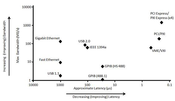
Three major factors affect bus performance: bandwidth, latency, and instrument implementation.
Figure 1. Compare the theoretical bandwidths versus latencies of mainstream test and measurement buses.
When creating an instrument control application, it’s important to consider the environment in which it will be deployed. Primary considerations include instrument distance from the PC and ruggedness specifications of the interface and cabling. Both elements play a major factor in making a decision as to which bus you should use for your instrument control system.
If your instruments are close to the PC (less than five meters), you have the flexibility of choosing from all bus types. If your instruments are far from the PC, for example, in another room or building, you should consider a distributed instrument control system architecture. A distributed instrument control system might include using extenders, repeaters, LAN/LXI, or a LAN converter (for example, Ethernet-to-GPIB converter).
If your instruments are in noisy environments, such as industrial settings, consider using an interface bus that offers protection from these environmental elements. For example, on a manufacturing floor, GPIB or USB would be a more appropriate choice because of its cable latching and ruggedized shielding specifications.
Keep in mind setup and installation when choosing your bus interface. For instrument control deployments that will be in areas such as a laboratory where many users will interact with the system, consider using the USB bus interface for the ease of use and consistent user experience. For instrument control systems that will be located where security may be an issue, you should be aware that Ethernet/LAN/LXI may not be permitted by your information technology department. If you decide that Ethernet/LAN/LXI is the best bus interface for your instrument control system and it will be deployed in a security-conscious environment, you should work with your information technology department throughout the design implementation process.
| Bus | Bandwidth (MB/s) | Latency (µs) | Range (m) (without extender) | Setup and Installation | Connector Ruggedness |
|---|---|---|---|---|---|
| GPIB | 1.8 (488.1) 8 (HS488) | 30 | 20 | Good | Best |
| USB | 60 (Hi-Speed) | 1,000 (USB) 125 (Hi-Speed) | 5 | Best | Good |
Ethernet/ LAN | 12.5 (Fast) 125 (Gigabit) | 1,000 (Fast) 1,000 (Gigabit) | 100 | Good | Good |
| PCI | 132 | 1.7 | Internal PC Bus | Better | Better Best (for PXI) |
| PCI Express | 250 (x1) 4,000 (x16) | 0.7 (x1) 1.7 (x4) | Internal PC Bus | Better | Better Best (for PXI) |
Table 1. Here’s a brief look at the most common instrument hardware buses.
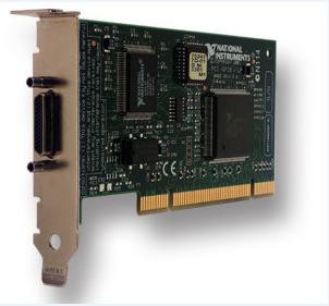
The General Purpose Interface Bus (GPIB) is one of the most common I/O interfaces in stand-alone instruments. GPIB is a digital, 8-bit parallel communications interface with data transfer rates up to 8 Mb/s. The bus provides one system controller for up to 14 instruments, and cabling is limited to less than 20 m. You can overcome both of these limitations by using GPIB expanders and extenders. GPIB cables and connectors are versatile and industrially graded for use in any environment.
Not being a PC-industry bus, GPIB is rarely available natively on a PC. Instead, you can use a plug-in board such as a PCI-GPIB or an external converter such as an NI GPIB-USB to add GPIB instrument control functionality to your PC.
Serial is a device communication protocol that is primarily found on older desktop and laptop PCs. Don’t confuse it with USB. Serial is a common communication protocol for instrumentation in many devices, and numerous GPIB-compatible devices feature an EIA232 port. EIA232 and EIA485/EIA422 may also be referred to as RS232 and RS485/RS422.
The concept of serial communication is simple. The serial port sends and receives bytes of information one bit at a time. Although this is slower than parallel communication, which transmits an entire byte at once, it’s simpler and you can use it over longer distances.
Typically, engineers use serial to transmit ASCII data. They complete communication using three transmission lines: ground, transmit, and receive. Because serial is asynchronous, the port can transmit data on one line while receiving data on another. Other lines are available for handshaking but are not required. The important serial characteristics are baud rate, data bits, stop bits, and parity. For two ports to communicate, these parameters must match.
Universal Serial Bus (USB) was designed primarily to connect PC peripheral devices, such as keyboards, mice, scanners, and disk drives, to PCs. Over the last several years, the number of devices that support USB connectivity has increased dramatically. USB is a plug-and-play technology where the USB host automatically detects when a new device has been added, queries the device for its identification, and configures the device drivers appropriately.
USB 2.0, is fully backward-compatible with both low-speed and full-speed devices. Its Hi-Speed mode is capable of data transfer rates of up to 480 Mbit/s (60 MB/s). The latest USB specification, USB 3.0, has a SuperSpeed mode, which has a theoretical data transfer rate of up to 5.0 Gbit/s.
Although USB was originally designed as a PC peripheral bus, its speed, wide availability, and ease of use make it attractive for use in instrument control applications. However, there are some drawbacks in its use for instrument control. First, USB cables are not industrially graded, which potentially allows data loss in noisy environments. Moreover, there is no latching mechanism for USB cables—the cables can be pulled out of the PC or instrument relatively easily. Also, the maximum cable length in USB systems is 30 m, including the use of inline repeaters.
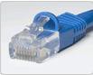
Ethernet is a mature technology that is widely used for measurement systems in other capacities, including general networking and remote data storage. With more than 100 million Ethernet-capable computers worldwide, Ethernet also offers an attractive option for instrument control. It’s defined as IEEE Standard 802.3 and offers network configurations that support theoretical data transfer rates of 10 Mbit/s (10BASE-T), 100 Mbit/s (100BASE-T), and 1 Gbit/s (1000BASE-T). The most common networks are 100BASE-T.
Instrument control applications over Ethernet can take advantage of the unique characteristics of the bus, including remote control of instruments, simplified instrument sharing, and easy publication of data results. Moreover, users gain the advantage of existing extensive Ethernet networks in their companies and laboratories. However, this advantage may pose a problem in some companies because it forces the involvement of network administrators in traditional engineering applications.
Additional drawbacks of Ethernet as an instrument control bus are actual transfer rates, determinism, and security. Although Ethernet networks can achieve theoretical transfer rates of 1 Gbit/s, these rates are rarely realized on a true network because of other network traffic overhead and inefficient data transfer. Moreover, because of the uncertainty of transfer rates, determinism is not assured in communicating across Ethernet. Finally, for sensitive data, users must take additional security measures to ensure data integrity and privacy.
The PCI bus is typically not used directly for instrument control but as a peripheral bus to connect GPIB or serial devices for instrument control. Also, because of its high bandwidth, PCI is used as a carrier bus for modular instruments where the I/O bus is built into the measurement device.
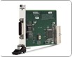
PXI (PCI eXtensions for Instrumentation) is a rugged PC-based platform for measurement and automation systems. PXI combines PCI electrical bus features with the rugged, modular, Eurocard-mechanical packaging of CompactPCI, and then adds specialized synchronization buses and key software features. This makes it both a high-performance and low-cost deployment platform for measurement and automation systems. These systems serve applications such as manufacturing test, military and aerospace, machine monitoring, automotive, and industrial test. Developed in 1997 and launched in 1998, PXI was introduced as an open industry standard to meet the increasing demands of complex instrumentation systems. Today, PXI is governed by the PXI Systems Alliance (PXISA), a group of more than 65 companies chartered to promote the PXI standard, ensure interoperability, and maintain the PXI specification. PXI is heavily used as a platform for modular instrumentation, providing an attractive alternative to traditional stand-alone instrumentation through compact, high-performance measurement hardware devices with integrated timing and synchronization resources.
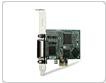
As with PCI, PCI Express is typically not used directly for instrument control but as a peripheral bus to connect GPIB devices to PCs for instrument control. But because of its tremendous speed, PCI Express can be used as a carrier bus for modular instruments.