对于步进电机,如何使用模拟反馈信号?
硬件: Motion Control>>Controllers>>PCI-7350, Motion Control>>Controllers>>PCI-7330, Motion Control>>Controllers>>PCI-7332, Motion Control>>Controllers>>PCI-7334, Motion Control>>Controllers>>PCI-7340, Motion Control>>Controllers>>PCI-7342, Motion Control>>Controllers>>PCI-7344, Motion Control>>Controllers>>PCI-7352, Motion Control>>Controllers>>PCI-7354, Motion Control>>Controllers>>PCI-7356, Motion Control>>Controllers>>PCI-7358, Motion Control>>Controllers>>PCI-7350, Motion Control>>Controllers>>PCI-7304, Motion Control>>Controllers>>PCI-7314, Motion Control>>Controllers>>PCI-7324, Motion Control>>Controllers>>PCI-7330, Motion Control>>Controllers>>PCI-7332, Motion Control>>Controllers>>PCI-7334, Motion Control>>Controllers>>PCI-7340, Motion Control>>Controllers>>PCI-7342, Motion Control>>Controllers>>PCI-7344, Motion Control>>Controllers>>PCI-7352, Motion Control>>Controllers>>PCI-7354, Motion Control>>Controllers>>PCI-7356, Motion Control>>Controllers>>PCI-7358
|
|
||||||||||||||||||||||||||||||||||||||||||||||||||
问题:
对于步进电机,我想使用模拟反馈信号。对此,我该如何实现?
解答:
基本上,设置步进电机的模拟反馈和设置伺服电机是一样的。即使您并没有用到编码器,您仍然需要为这个并不存在的编码器定义每转的脉冲个数。
接下来的4个步骤将指导您如何配置您的步进电机工作在模拟反馈模式下。
- 将模拟反馈信号连接到您将要用的轴的模拟输入端。对于具体的针脚定义,请参考您的运动控制板卡的用户手册或者您的通用运动接口(UMI)手册。
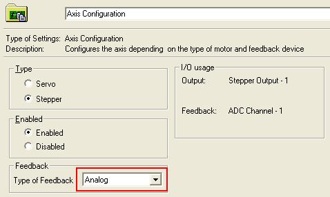
- 在MAX里的Axis Configuration中(请选择连接您的步进电机的轴),选择Types of Feedback为Analog。
- 在MAX 里的“ADC Settings”中,选择适合您模拟反馈传感器的电压范围。
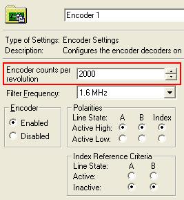
- 在“Encoder Settings”中,设置编码器每转脉冲的个数,使之等于步进电机每一转过程中ADC的步数。

相关链接:
Product Manuals: National Instruments 7330 User Manual
Product Manuals: National Instruments 7340 User Manual
Product Manuals: NI 7350 User Manual
Product Pages: Universal Motion Interfaces
附件:
|
|
||||||||||||||||||||||||||||||||||||||||||||||||||
报告日期: 12/10/2006
最近更新: 12/17/2006
文档编号: 3VMMB7AJ