From Friday, April 19th (11:00 PM CDT) through Saturday, April 20th (2:00 PM CDT), 2024, ni.com will undergo system upgrades that may result in temporary service interruption.
We appreciate your patience as we improve our online experience.
From Friday, April 19th (11:00 PM CDT) through Saturday, April 20th (2:00 PM CDT), 2024, ni.com will undergo system upgrades that may result in temporary service interruption.
We appreciate your patience as we improve our online experience.
Temperature is a very common measurement with verification, validation, and production test. This document provides context and information to help you select the best temperature sensor for your application needs. After you decide on your sensors, you can consider the required hardware and software to properly condition, acquire, and visualize temperature measurements. You can also consider any extra signal conditioning you may need.
You can choose from a variety of sensors to translate temperature phenomena into a measurable signal. Three common sensor varieties are the thermocouple, RTD, and thermistor. You can use other temperature measurement sensors, such as ICs or Fiber Bragg Gratings, but they will not be discussed in this resource.
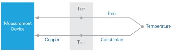
Thermocouples operate under the principle known as the Seebeck effect. When two wires made of dissimilar metals are joined and heated at one end, a thermoelectric circuit is formed that causes a measurable voltage differential known as the Seebeck voltage at the “cold” end. A given pairing of metals varies in temperature range, sensitivity, and error based on the properties of those metals.
Figure 1. Illustration of the Seebeck Effect
Each type of thermocouple consists of a unique pairing of metals. You need to understand the operating specifications of the thermocouple type you select for your temperature measurement. Some thermocouples offer a wide temperature range at the expense of a very nonlinear voltage-temperature relationship, while others provide a smaller (but more linear) temperature range.
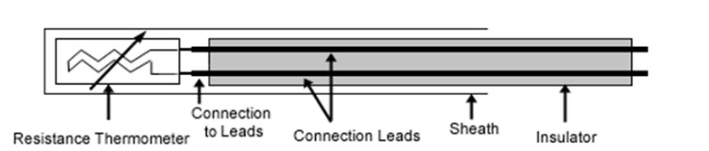
Resistance temperature detectors (RTDs) are active measurement devices that operate by changing resistance with changes to ambient temperature. RTDs are typically constructed with a ceramic or glass core and a thin winding of metal that’s often platinum due to its stability.
Figure 2. Basic Resistance Thermometer Components
Alternative configurations use different insulation and/or winding materials, which result in different performances and temperature ranges. Another option, a thin-film RTD, consists of a thin layer of metal in between layers of insulating material. This style is best suited for surface temperature measurements because it provides more uniform contact across the surface of the RTD.
The key to the ability of an RTD to measure temperature is the thermal properties of the metal winding. If you understand these properties well, you can reliably predict the temperature at a measured resistance. The predictable resistance-temperature relationship leads to an accurate temperature measurement device.
Thermistors, like RTDs, are active measurement devices that operate by changing resistance with changes to ambient temperature. They consist of a metal oxide semiconductor pressed into a small bead, disk, wafer, or other container and coated with epoxy or glass. Since thermistors are constructed of semiconductor materials, they provide the best sensitivity of any measurement device and are ideal for measuring smaller temperature changes. They also generally have a much higher resistance than an RTD. Unlike an RTD, a thermistor is typically a negative temperature coefficient device, which means its resistance decreases with an increase in temperature
With three different types of temperature sensors, it’s important to narrow the choice between these three at a high level before taking into consideration the differences and types of each sensor respectively.
If you are unsure about choosing between the three common options, first review some basic and high-level advantages and disadvantages in Table 1. If you need some specifics, review the sensor characteristics and comparisons in Table 2.
After selecting the temperature sensor you will be using, thermocouples, RTDs, or thermistors, you can review additional considerations for each sensor:
Advantages and Disadvantages of Temperature Sensors
Depending on what your limitations or needs are, from budget to hardware capabilities, each sensor has advantages and disadvantages with each sensor type. It’s important to understand and prioritize test needs to pick the best sensor for your application.
Table 1. Advantages and Disadvantages of Temperature Sensor Types
Temperature Sensor Characteristics
When selecting a sensor, understand the impact of each characteristic on your measurements and be sure to select a sensor that aligns closely with your project requirements. Use the following characteristics to define your temperature sensor capabilities and performance. These characteristics apply to all temperature sensor types but with some caveats and corner cases. Table 2 compares the different characteristics of the three common sensors.
After selecting the temperature sensor you will use, thermocouples, RTDs, or thermistors, review further sensor considerations before choosing the right sensor for your applications.
Table 2. Comparison of Temperature Sensor Types
Temperature Range
The temperature range of a sensor defines the temperatures at which the sensor is rated to operate safely and provide accurate measurements.
By understanding the full range of temperature, you can expose your sensor and help prevent sensor damage while ensuring better measurements.
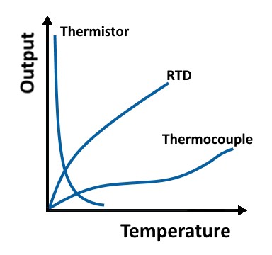
An ideal sensor would have a perfectly linear response: a unit change in temperature would result in a unit change in voltage output across the entire temperature range of the sensor.
However, no sensor is perfectly linear. Figure 3 offers an idea of the temperature-to-voltage response of the three sensors this resource examines.
Figure 3. Temperature-to-Output Response of Sensors
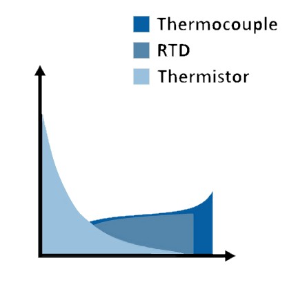
The sensitivity of a given sensor indicates the percent change in measurable output for a given change in temperature. A more sensitive sensor, like a thermistor, can more easily detect small changes in temperature than a less sensitive sensor, like a thermocouple.
This sensitivity, however, comes at the expense of linearity. This can be an important factor when determining the ideal sensor choice for the temperatures you are measuring. If you intend to capture fraction-of-a-degree changes over a small temperature range, a thermistor or an RTD is more ideal. For capturing larger temperature changes over a wider range of temperatures, a thermocouple may suffice. Figure 4 gives a relative idea of the voltage.
Figure 4. Sensitivity of Various Temperature Sensor Types
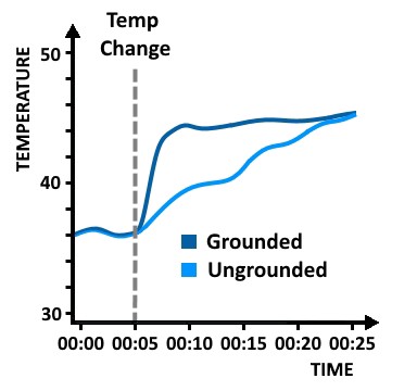
Response time is the measure of time a sensor takes to respond to a change in temperature. Many factors can cause response times to increase or decrease.
A larger RTD or thermistor, for example, has a slower response time than a smaller one. In exchange for this drawback and poorer thermal shunting, a larger RTD or thermistor is less susceptible to self-heating
errors. Similarly, ungrounded thermocouple junctions provide a slower response time in exchange for electrical isolation. Figure 5 shows the relative difference in response times for ungrounded and grounded thermocouples.
Figure 5. Response Time of Grounded versus Ungrounded Thermocouples
The stability of a temperature sensor is an indication of its ability to maintain a consistent output at a given temperature.
Material plays a key role in the stability of a given sensor. RTDs are often constructed of platinum for this reason as well as to ensure low reactivity. The substrate to which the platinum is bonded, however, may deform under prolonged exposure to high temperatures, which can cause additional and unexpected strain that leads to a change in measured resistance.
As with any measurement application, understanding your accuracy needs is critical in ensuring reliable results. Your sensor and measurement hardware selections play a significant role in absolute measurement accuracy, but smaller details such as cabling, relative proximity to other equipment, shielding, grounding, and so on can all affect accuracy as well.
When selecting a sensor, note the specified tolerances and any factors that might impact that specification (for example, prolonged exposure to high temperatures). Also be careful to select a sensor and measurement device with similar accuracies. A tight tolerance RTD comes at a greater cost, but you may not achieve the additional accuracy if you use a low-quality measurement device
To ensure your temperature sensors remain operational for the duration of your application, you need to understand the environment in which you are deploying them. Some sensors (thermocouples, for example) are inherently more durable because of their construction. The metals selected for a particular thermocouple, however, have different resistances to corrosion. Furthermore, a sensor encased in an isolating mineral and a protective metal sheath is more resistant to wear and corrosion over time, but it
costs more and offers less sensitivity. You should also note that different sensor configurations may have special mounting requirements to ensure a solid physical and thermal connection.
As with any aspect of a project, cost can be a key limiting factor. In high-channel-count applications, for example, the linearity benefits of RTDs may be outweighed by the relative increase in cost versus thermocouples. You must also consider the added cost of wiring, mounting, and signal conditioning when considering total system cost.
| Sensor | Advantages | Disadvantages |
| Thermocouples |
|
|
| RTDs |
|
|
Thermistor |
|
|
| Characteristic | Thermocouple | RTD | Thermistor |
| Temperature Range | Excellent -210 °C to 1760 °C | Great -240 °C to 650 °C | Good -40 °C to 250 °C |
Fair | Good | Poor | |
Low | Medium | Very High | |
Medium to Fast | Medium | Medium to Fast | |
Fair | Good | Poor | |
Medium | High | Medium | |
No | Yes, Minimal | Yes, Highly | |
Excellent | Good | Poor | |
Lowest | High | Low | |
| Signal Conditioning Requirements | Cold-Junction Compensation Amplification Open Thermocouple Detection Scaling | Excitation Lead Resistance Correction Scaling | Excitation Scaling |
Consider four main application factors when choosing your temperature sensors:
1. Understand the measurement application and requirements.
2. Determine the temperature ranges that you must measure.
3. Consider the environment in which you are deploying the sensors.
4. Consider how you are mounting your sensors and select an appropriate mounting style to maximize the thermal connection.
After you’ve narrowed between thermocouples, RTDs, and thermistors for your temperature measurement, there are some specific considerations for each sensor category that influence and impact the type of sensor to purchase.
Thermocouple Sensor Considerations
There are a variety of thermocouple types and constructions. The main two aspects of thermocouple sensors are the type and the sheathing configurations.
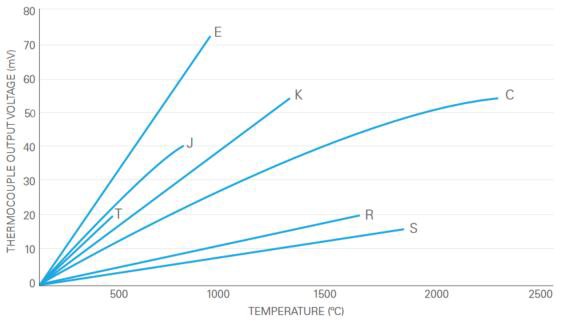
Types are generally defined by a letter designation—common types are E-, J-, T-, K-, C-, R-, and S-type. NI’s temperature hardware works with all National Institute of Standards and Technology (NIST) standard thermocouples. The thermocouple type defines the metals used to create the thermocouple; therefore, it also defines the operating range, accuracy, and linearity of the thermocouple.
The following graphs depict the voltage response of various thermocouple types over a range of temperatures.
Figure 6. Temperature Response of Different Thermocouple Types
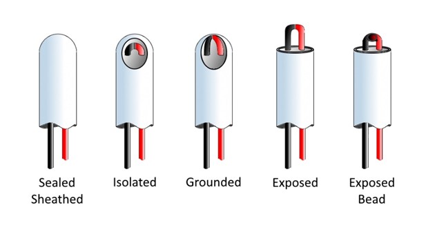
In addition to the type of thermocouple, you must choose a sheathing configuration. Some of these options are shown in Figure 7, including grounding, isolated, sealed, and exposed.
In addition to the type of thermocouple, you must choose a sheathing configuration. Some of these options are shown in Figure 7, including grounding, isolated, sealed, and exposed.
Figure 7. Options for Thermocouple Sheathin
Each configuration has advantages and disadvantages regarding response time, noise immunity, and safety. Table 3 gives an overview of the impact of each configuration option.
Table 3. Overview of Thermocouple Junction Configurations
The various types of RTDs have three primary defining attributes: number of lead wires, wire materials, and physical construction.
Number of Lead Wires
Since RTDs are active sensors, they require external excitation to produce a measurable voltage drop that can be translated into resistance. Resistance values are generally very low, meaning lead-wire resistance can cause less accurate measurements. Because of this, RTDs often come in multiwire configurations. The number of lead wire configurations can range from 2 to 4.
Two-wire RTDs are the simplest to use, but they can affect measurement accuracy if the resistance of the lead wires is significant relative to the measured resistance of the RTD element.
Figure 8. Two-Wire RTD
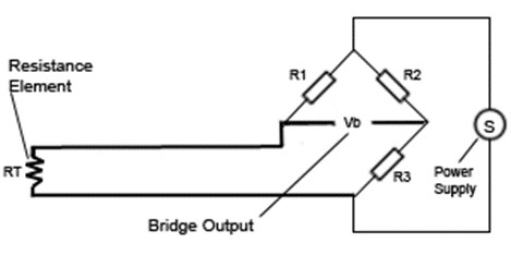
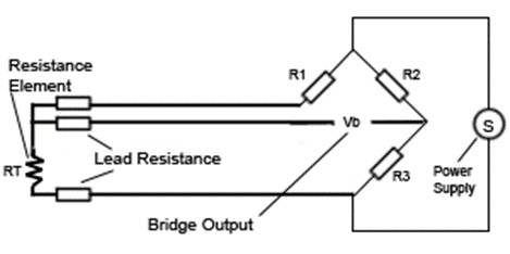
Three-wire RTDs are the most common in industrial applications. They allow the measurement hardware to characterize and correct for lead-wire resistance, which results in a more accurate measurement. Inconsistencies in the lead-wire resistance, however, can lead to unexpected measurement errors.
Figure 9. Three-Wire RTD
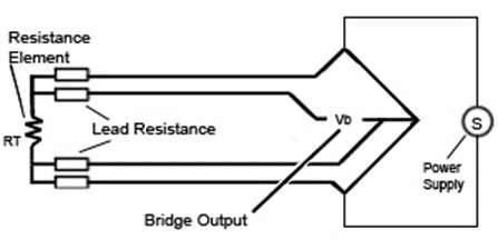
Four-wire RTDs provide separate paths for both excitation and resistance measurement. This allows for lead-wire resistance correction as well as the isolation of any noise in the excitation signal. Four-wire RTDs are also immune to mismatched lead-wire resistances, but they require measurement hardware capable of a four-wire resistance measurement.
Figure 10. Four-Wire RTD
Wire Material
Each RTD-led wire configuration can be made up of different materials. Two key factors that influence the selection of wire materials are deployment environment and temperature range. Understanding the testing environments can limit what materials can be used under different constraints, such as can it withstand expected water submersion, chemicals, and/or abrasion. Wire material and sizing also impact lead resistance, depending on lead-wire configuration.
Physical Construction
The physical construction is application-specific. Consider how the sensor must be mounted, any electrical isolation requirements, and the type of medium the sensor will be immersed in (liquid, gas, solid surface, and so on).
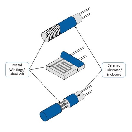
Available configurations include basic RTD elements, thin-film surface elements, and probes for which the RTD element is encased in a metal sheath and possibly electrically isolated.
Figure 11. RTD Construction Styles
Thermistor Sensor Considerations
As with any temperature sensor, an important factor to consider with thermistors is material composition and its subsequent impact on temperature range, sensitivity, accuracy, and so on.
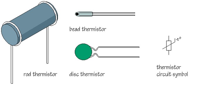
Sensor vendors may provide different metal-oxide compositions and/or casing materials that affect how the sensor can be mounted as well as chemical/abrasive resistance capabilities. Thermistors also come in a variety of physical configurations suited for different applications. Figure 12 shows some of these options.
Figure 12. Thermistor Configurations
Unlike RTDs, thermistors rarely require a configuration other than two-wire because their resistance is several orders of magnitude greater than any lead-wire resistance that may be present. The impact of lead-wire resistance on measured resistance is minimal and often negligible.
| Sensor | Advantages | Disadvantages | ||
| Thermocouples |
|
|
Junction Configuration | Advantages | Disadvantages |
Exposed | Fastest response (~0.1 s to 2 s) | Ground loop and noise potential no chemical protection most prone to physical damage |
Exposed Bead | Fast response (~15 s) | Ground loop and noise potential no chemical protection prone to physical damage |
Sealed and Grounded | Physical and chemical protection | Slow response (~40 s) Ground loop and noise potential |
Sealed and Isolated | Physical and chemical protection electrical protection (avoids ground loops and noise) | Slowest response (~75 s) |
NI offers E-, J-, K-, and T-type thermocouples with a variety of lengths from 0.6 m to 2 m, and characteristics such as fiberglass, grounded, and ungrounded.
In addition to the characteristics of the sensors themselves—operating range, sensitivity, linearity, response time, and so on—you must consider the requirements each sensor type imposes on the measurement hardware.
Each type of temperature sensor requires some level of signal conditioning to adequately acquire and digitize the measured signal for processing. The measurement hardware you select can be just as important in ensuring accurate measurements as the sensor and can mitigate or exacerbate the shortcomings of each sensor type.
Signal conditioning for all three sensor types (RTDs, thermistors, thermocouples):
Signal conditioning specifically for thermocouples:
Signal conditioning specifically for RTDs and thermistors:
Some of NI’s temperature measurement hardware includes built-in signal conditioning. To better familiarize yourself with the measurement hardware necessary for temperature measurements, download the Engineer's Guide to Accurate Sensor Measurements.
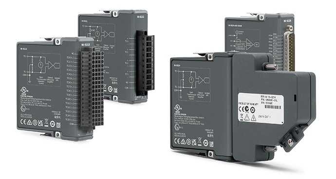
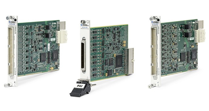
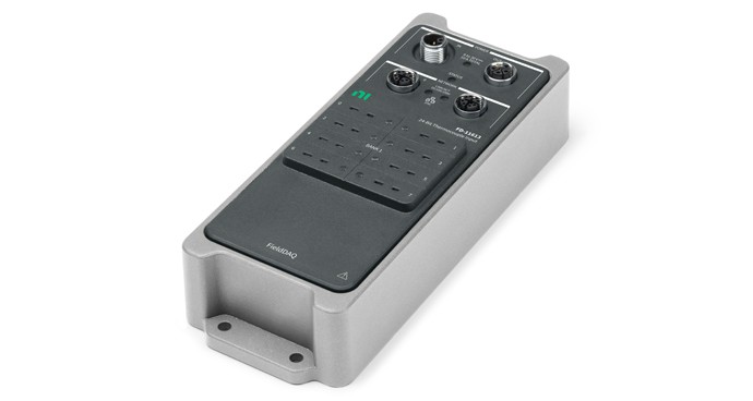
After you know your sensor or test needs, deciding on the hardware to collect that data is the next important step. The acquisition hardware’s quality determines the quality of the data you collect.
NI offers a range of Temperature Measurement Hardware that is designed to acquire temperature data and is compatible with all NIST thermocouples as well as some RTD and thermistor sensors.
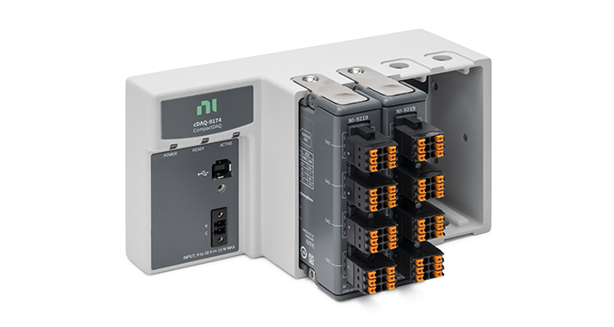
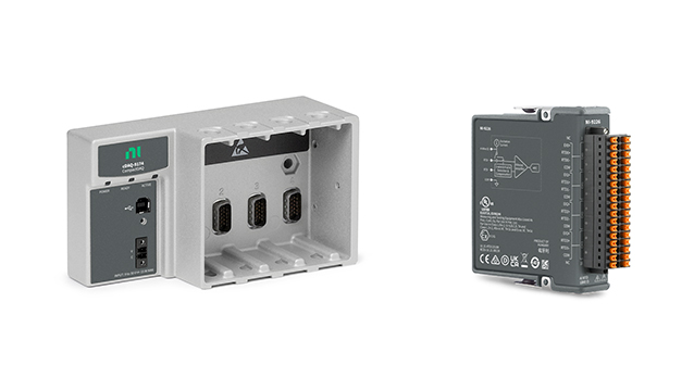
Simple Hardware Setup
The CompactDAQ Temperature Measurement Bundle simplifies connecting your thermocouple with a bundle of temperature input module(s) and a CompactDAQ chassis.
The following products can interface with torque sensors. These products also work pressure, force, and torque measurements. Learn more about measuring pressure with bridge-based or other pressure sensors, strain with strain gages, or load with bridge-based load cells to choose the right sensors and use with NI products.