Introduction
As part of any digital logic fundamentals course, it is important that students learn the importance and process of logic simplification. Finding equivalent circuits that can be achieved with fewer components can often reduce manufacturing costs and improve reliability.
This tutorial will provide an example of how Multisim can help students understand the process of logic simplification. Multisim allows students to work through the process of applying the theory, creating a logic diagram, understanding and simplifying the response, all while demonstrating these skills using hardware.
Simulation of Logic for Simplification
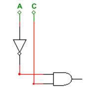
In this tutorial we are going to work on the simplification of the logic diagram below. Currently, this contains a series of NOT gates and NOR gates. In simplifying this diagram we want to reduce the overall number of logic gates.
Before attempting to simulate this circuit, the student should try to apply theory to derive the Boolean expression for the circuit and use Boolean algebra to attempt to simplify it. Multisim allows students to check their thought processes and produce verified results.
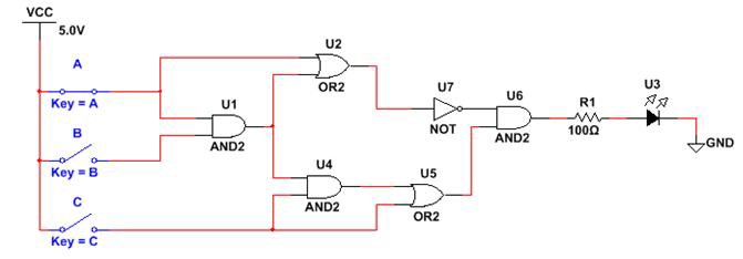
- Open a new schematic and create the logic diagram above. Alternatively, drag the snippet contained below onto the Multisim schematic.
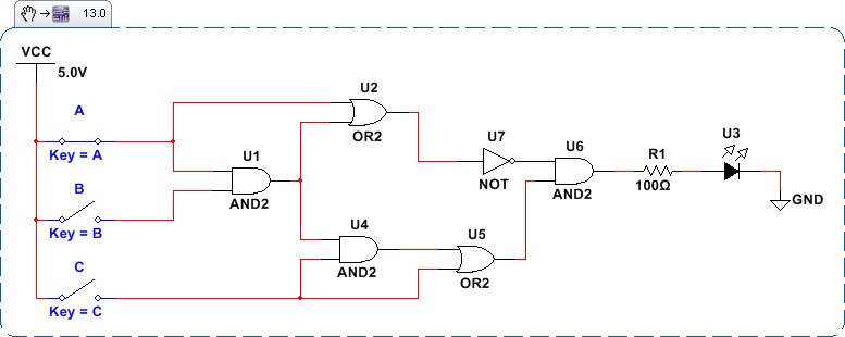
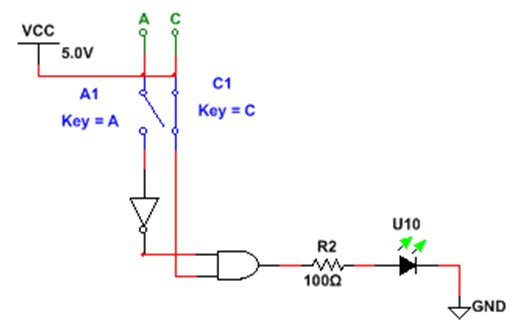
- The logic diagram contains interactive switches and an LED. This allows us to immediately simulate the circuit and view the response. Run the simulation and click on the switches to operate them. View the response for different switch combinations.
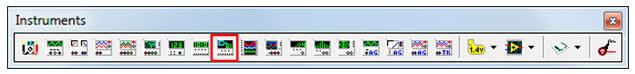
- As well as this interactive execution, we can use the Logic Converter instrument to generate a truth table and Boolean expression. This will help us simplify the circuit. Select the Logic Converter from the instruments toolbar.
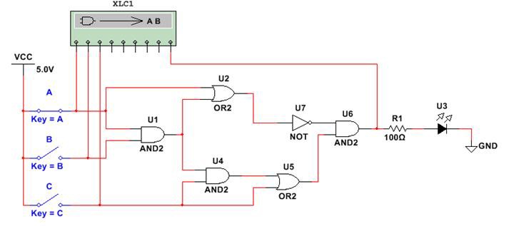
- Connect the logic converter to the schematic as shown below:
- Open the user interface for the logic converter by double clicking on it. The logic analyzer allows us to generate a truth table for the response of the circuit.
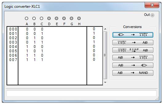
From the truth table we can see that the output is high when input A is high and input C is low.
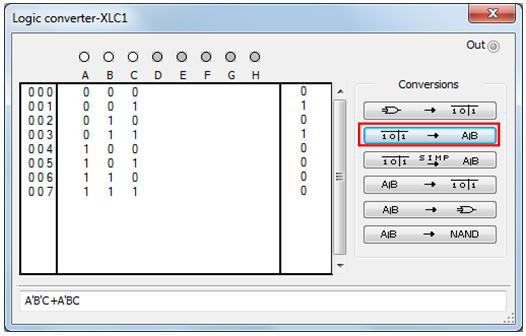
- Next we can generate an expression for the logic by clicking on the next conversion function. The logic converter generates the expression:
A’B’C + A’BC
- This can be simplified further because input B does not affect the output. Click the next conversion button to simplify the expression.
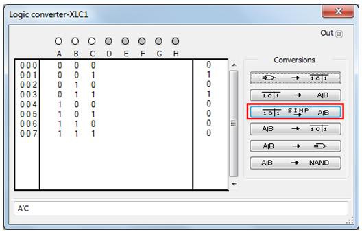
- At this point we have simplified the expression to:
A’C
Still using the Logic Converter, we can use this expression to generate a logic diagram. To do this click the conversion highlighted below.
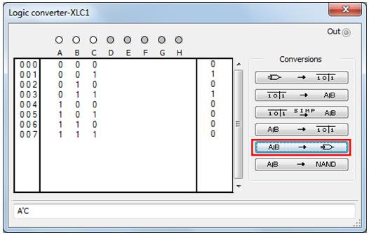
This will generate a simple AND gate with one of the inputs inverted through a NOT gate.
- Try connecting this logic to a the VCC source, switches, and an LED to confirm the response of the logic diagram:
Export Digital Logic to Hardware
Once the simplification of the logic diagram is complete, we can deploy this to the hardware.
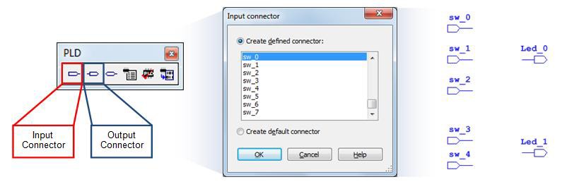
- Create a new PLD schematic for the Digilent board being used. Instructions on creating the PLD schematic can be found here: Getting Started with Digilent Boards in Multisim.
- Add terminals for switches 0, 1, 2, 3 and 4 (SW_0, SW_1, SW_2, SW_3, SW_4), as well as LEDs 1 and 2, (Led_0, Led_1).
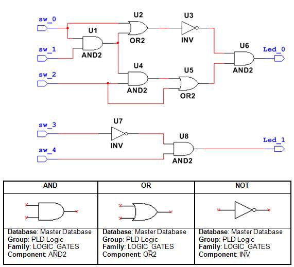
- Create the logic diagrams as shown in the figure below.
- When the schematic is complete it can be deployed to the hardware. Details on the process for deploying to the Digilent teaching boards can be found here: Getting Started with Digilent Boards in Multisim .
- Use the switches and LEDs denoted in the schematic to confirm that the hardware response is identical for the original and the simplified circuit.