IP to FPGA Conversion Utility
Overview
The IP to FPGA Conversion Utility supports the conversion of MathWorks MATLAB Simulink® models into NI FPGA bitfiles. An earlier approach used a manual process that required LabVIEW expertise. In contrast, this utility auto-converts a given Simulink model into a bitfile.
This document contains information on how to use the IP to FPGA Conversion Utility. It is intended for those who want to convert Simulink models into FPGA bitfiles for deployment to the supported NI FPGA hardware. For more information on supported hardware, refer to readme.
The document also discusses how to interface with the generated bitfile using VeriStand and other applications.
Note: This process assumes familiarity with Simulink. For more information and examples of Simulink designs, refer to the MathWorks documentation.
Contents
- Installation Instructions
- Limitations
- Converting Simulink Models into Bitfiles
- Importing a Bitfile into VeriStand
- Modifying the Configuration Template File
- Commands Table
- Advanced Modifications
Installation Instructions
To install the IP to FPGA Conversion Utility, refer to readme.
Limitations
The IP to FPGA Conversion Utility has the following limitations:
- No support for double precision ports
- Only registers CPU-FPGA communication through Read/Write controls
- No support for purely combinatorial circuits, such as circuits without clocks
Converting Simulink Models into Bitfiles
Software Requirements
- MATLAB Simulink® with HDL Coder license (r2020a or above)
- For LabVIEW and driver version requirements, refer to readme
Steps
- Open the model you want to convert into an NI FPGA bitfile in Simulink.
Note: For Simscape models, use the Simscape HDL Workflow Advisor to convert an existing model into a Simulink HDL Implementation model. - Navigate to the Configuration Parameters window.
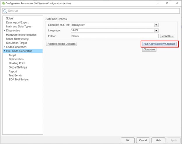
Note: For more information on the Simulink environment, refer to their documentation. - In the navigation pane, click HDL Coder Generation.
- Set the Language to VHDL.
Note: Verilog is not supported. - Set the Folder where Simulink will generate the VHDL code.
- Click Run Compatibility Checker to confirm the compatibility of the model.
- In the navigation pane under HDL Code Generation, click Target and enter a Target Frequency (MHz).
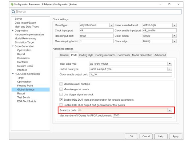
- (Optional): If your model has an array or complex ports, in the navigation pane click Global Settings and set Scalarize ports to on.
- Save the model (.slx) and generate the HDL code.
- Ensure that all LabVIEW and LabVIEW FPGA licenses are activated on the machine you are running the IP to FPGA Conversion Utility.
Note: You can skip this step during subsequent bitfile conversions. - Open the Command Line and enter ip2fpgaCLI.exe.
- Enter the create-config command to create a configurations template file.
Note: For more information on the create-config command, refer to the Commands Table.
Note: When running this command for the first time in LabVIEW 2021 and later, the Security Warning: Run When Opened dialog box will open. Enable Remember this choice in the permission list and click Run.
- (Optional): To have the configuration template file map the model ports to Board I/Os, refer to Modifying Configuration Template File. By default, model ports map to registers.
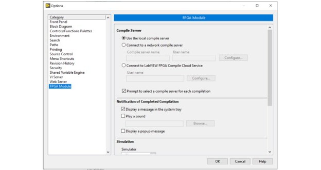
- Open LabVIEW and select the Compile Server option from Tools >> Options.
Note: You can skip this step during subsequent bitfile conversions. For more information on compiling options, refer to NI LabVIEW FPGA Compilation Options.
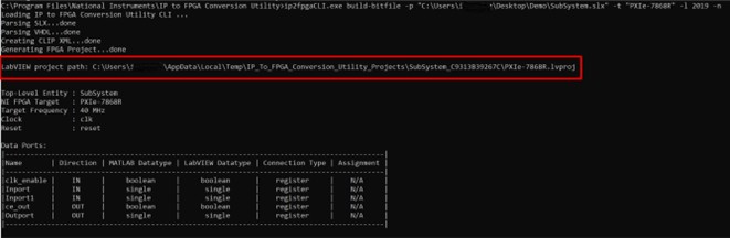
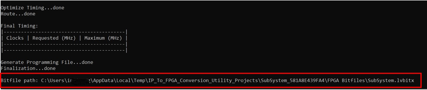
- Enter the build-bitfile command to generate the bitfile.
Using this command causes the IP to FPGA Conversion Utility to display information in the command line output. This information includes the created LabVIEW Project Path, Data Ports table, Estimated Device Utilization, Final Device Utilization, Bitfile Path, and more.
Note: For more information on build-bitfile command, refer to the Commands Table.

Importing a Bitfile into VeriStand
Software Requirements
Steps
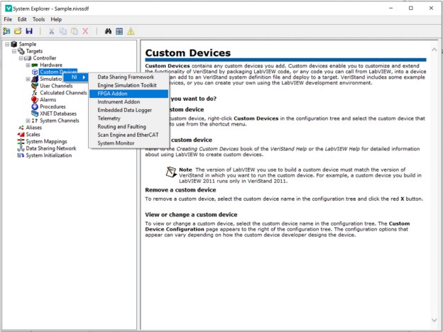
- After generating a bitfile, import that file into VeriStand through the FPGA Addon Custom Device.
The path to the bitfile can be found in the command line output.
- Open VeriStand System Explorer to add the FPGA Addon Custom Device.
Note: For more information, refer to the FPGA Addon Quick Start Guide on GitHub.
Interfacing with the Bitfile from other Applications
In addition to VeriStand, you can interface with the bitfile from the following applications:
Modifying the Configuration Template File
The configuration file allows the user to map a model port to the supported NI FPGA Board I/O or to registers. A template configuration file can be created by using the create-config command.
Note: By default, all model ports map to registers.
The configuration file also contains information on the available Board I/Os for the selected NI FPGA target. This helps with mapping model ports to Board I/Os.
Before modifying the configuration file, read the file’s Board I/O details. Understanding the direction and datatype of the model port and Board I/O is essential to determining the correct connection configuration. The following is a snippet of a model port mapped to a Board I/O.
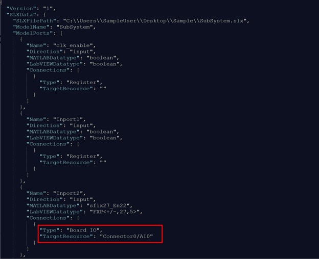
Note: Using the build-bitfile command will trigger a data loss warning if the model port bitness does not match the mapped Board I/O bitness.
Commands Table
Command Options | Description | Example | |
|---|---|---|---|
-v, --verbose | Increases output logging verbosity. | ||
| create-config | Creates a configuration template file for the specified NI FPGA. This file can be used to map model ports to a Board I/O.
The configuration file can be passed on as an option for the build-bitfile command
| ip2fpgaCLI.exe create-config -p "C:\Users\SampleUser\Desktop\Sample\SubSystem.slx" -t "PXIe-7867R" -l 2019 -o "C:\Users\ SampleUser\Desktop\Sample\SubSystem.JSON" | |
-p, --project=<value> | Specifies a path to a Simulink (.slx) project. Simulink must successfully generate HDL code before using this command. | ||
-t, --target=<value> | Specifies the NI FPGA target type to generate the bitfile. Enter the value as either PXIe-7867R or PXIe-7868R. | ||
-l, --lvversion=<value>(optional) | Specifies the LabVIEW version used to compile the bitfile. If not specified, the default is the latest LabVIEW version. | ||
-o, --output=<value>
| Specifies the path for saving the configuration (.json) file. | ||
build-bitfile |
| Builds a bitfile from the provided SLX file and targeting the specified NI FPGA Board.
| ip2fpgaCLI.exe build-bitfile -p "C:\Users\SampleUser\Desktop\Sample\SubSystem.slx" -t "PXIe-7867R" -l 2019 -c "C:\Users\ SampleUser \Desktop\Sample\SubSystem.JSON" |
| -p, --project=<value> | Specifies a path to a SLX file. Simulink must successfully generate HDL code before using this command. |
|
| -t, --target=<value> | Specifies the NI FPGA target type to generate the bitfile. Enter the value as either "PXIe-7867R" or "PXIe-7868R". |
|
| -l, --lvversion=<value>(optional) | Specifies the LabVIEW version used to compile the bitfile. If not specified, the default is the latest LabVIEW version. |
|
-n, --nocompile (optional) | If present, execution will stop after generating the LabVIEW FPGA project. No bitfile will be compile.
For more information on this command, refer to Advanced Modifications. | ||
-c, --configfile=<value> (optional) | Specifies the path to a Configuration file (.json). If not specified, the default is to map model ports to board I/Os. | ||
generate-lvproj |
| Generates a LabVIEW FPGA Project (.lvproj) for the specified FPGA board from the provided Simulink model (.slx) or .nihdlwprj file | ip2fpgaCLI.exe generate-lvproj -p "C:\Users\SampleUser\Desktop\Sample\SubSystem.slx" -t "PXIe-7867R" -l 2019 -c "C:\Users\ SampleUser\Desktop\Sample\SubSystem.JSON" |
-p, --project=<value> | Specifies a path to a Simulink model (.slx) or . nihdlwprj file. As a prerequisite, Simulink must successfully generate HDL code. | ||
-t, --target=<value> | Specifies the NI FPGA target type to generate the bitfile. Select either "PXIe-7867R" or "PXIe-7868R". | ||
-l, --lvversion=<value>(optional) | Specifies the LabVIEW version used to compile the bitfile. If not specified, the default is the latest LabVIEW version. | ||
-c, --configfile=<value> (optional) | Specifies the path to an FPGA Board IO Configuration file (.JSON). | ||
compile-lvproj |
| Builds a bitfile from the provided LabVIEW FPGA project file (.lvproj). | ip2fpgaCLI.exe compile-lvproj -p "C:\Users\SampleUser\Desktop\Sample\PXIe-7867R.lvproj" -l 2019 |
| -p, --project=<value> | Specifies the path to a LabVIEW FPGA project file (.lvproj).
|
|
| -l, --lvversion=<value> (optional) | Specifies the LabVIEW version used to compile the bitfile. If not specified, the default is the latest LabVIEW version. |
|
Note: Use NI FPGA Bitfile Generation Workflow in the HDL Coder Workflow advisor to generate the .nihdlwprj file. HDL Coder Support Package for NI FPGA Hardware is required to be installed to use this workflow. Execute Generate Project step to create the .nihdlwprj file. The file will be found in hdl_prj\ip2fpgacli
Advanced Modifications
LabVIEW users may want to make the following changes:
- Add another custom IP
- Update the Xilinx Implementation Strategy
- Configure the Board I/O properties before generating a bitfile
To do so, open the LabVIEW project generated by the build-bitfile command using the command option -n:
ip2fpgaCLI.exe build-bitfile -p "C:\Users\SampleUser\Desktop\Sample\SubSystem.slx" -t "PXIe-7868R" -l 2019 -n
Use the generated LabVIEW project file to make the necessary modifications. You can find this file at the path displayed in the output window.