Engineering Teaching Resources
Implement a hands-on approach to engineering education with resources developed by leaders in education.
Accelerate Student Discovery
Engineering educators are preparing students to design the systems that will tackle the world’s grand challenges. This requires engaging, hands-on curriculum that inspires students and puts theory into practice. Hear from one of our authors on how the studio-style curriculum at the University of Virginia improved student engagement. Then, browse our portal to find open-ended projects and ABET-aligned laboratories to accelerate student discovery in key topics and application areas.
Featured Lab Manuals
Introduction to Circuits
This course covers the fundamental concepts of circuit theory and analysis through simulation in Multisim Live, and real-life circuit-building. Designed for NI ELVIS III.
Energy Systems Analysis
Students complete hands-on activities to investigate the essential functionality and behavior of energy conversion systems from AC-DC, DC-DC, DC-AC, and AC-AC. Designed for NI...
Power Electronics
Students complete hands-on labs that cover the fundamentals of DC-DC linear regulators, DC-DC buck regulators, DC-AC inverters, and AC-DC rectifiers. Designed for NI ELVIS III.Featured Labs
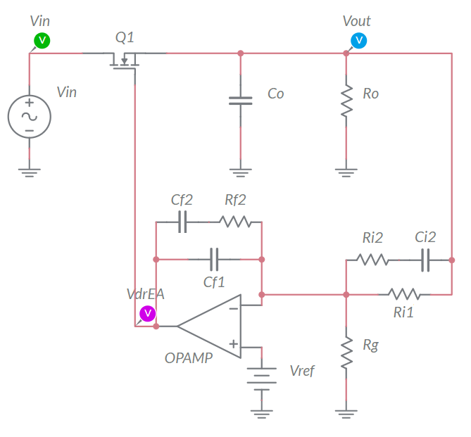
Linear Regulator in Closed Loop Operation
In this lab, students investigate the impact of loop gain on the ability of a closed loop linear regulator to reject noise and changes in the output voltage. Designed for NI ELVIS...
RLC Circuits
In this lab, students will learn about RLC circuits and how to calculate their different parts, and then finally how to build them on a bread board. Designed for use with NI ELVIS...
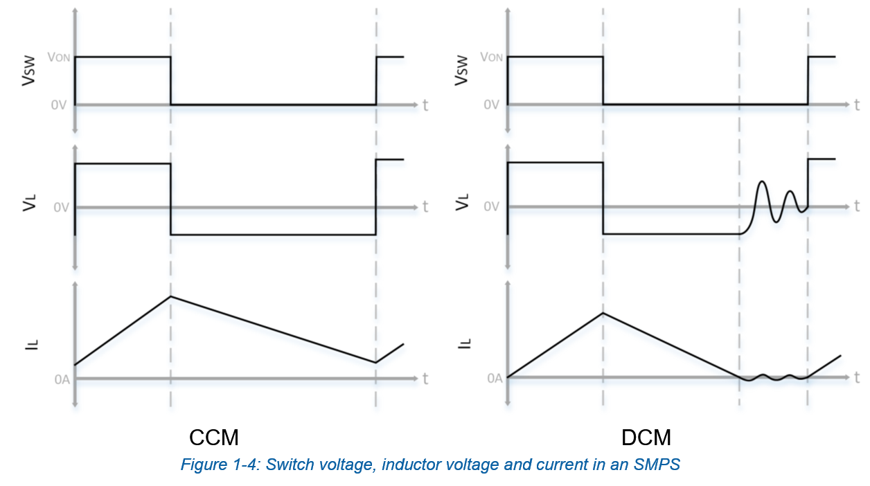
DC Power
In this lab, students complete hands-on activities that focus on the conversion of DC power into either higher or lower potentials using the SMPS module. Designed for NI ELVIS...
Featured Lab Manuals

Control System Design and Analysis
Students complete activities that progress from basics in modeling and control to more complex control strategies like hybrid and digital control. Designed for NI ELVIS III and...
Fundamentals of Mechatronic Actuators
Students complete hands-on activities to control and compare common motors in order to make wise system design decisions. Designed for NI ELVIS III
Mechatronic Systems Analysis
Students interact with a complete mechatronic system from low-level integration, through sub-systems and processes, to the higher-level automation algorithms. Designed for NI...Featured Labs
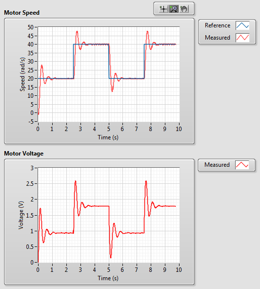
DC Motor Speed Control
In this lab students learn about qualitative and quantitative PI control design through a hands-on lab about DC motor speed control. Designed for NI ELVIS III and LabVIEW.
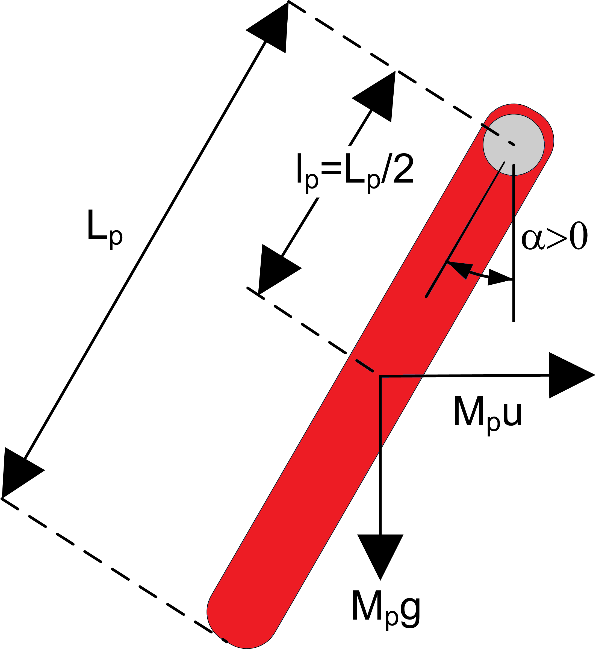
Inverted Pendulum Control
In this lab students will learn about inverted pendulum control through hands-on application of the concepts. Designed for use with NI ELVIS III and LabVIEW.
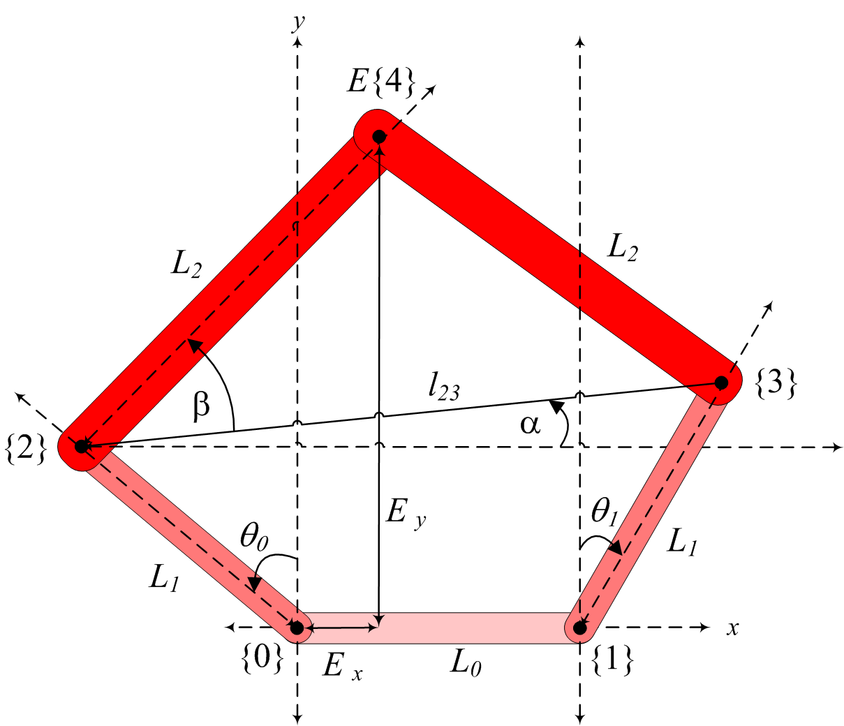
Controlling Manipulators
Students complete activities for PID Joint Control, Forward Kinematics, and Inverse Kinematics using the Quanser Mechatronic Systems Board and LabVIEW. Designed for NI ELVIS III.
Featured Lab Manuals

myDAQ Projects for Engineering Students
myDAQ Projects for Engineering Students teaches introductory engineering concepts through engaging DAQExpress workbooks exploring data acquisition, transducer interfacing, and...
Fundamentals of Mechatronic Sensors
In this lab students will complete hands-on activities to measure, calibrate, and analyze common physical properties/phenomena. Designed for NI ELVIS III.
Student Projects for Measurements and Instrumentation
Students complete hands-on labs that explore the different stages of taking a measurement, and then move on to open-ended projects where they can design their own measurement...Featured Labs

ADC and Sampling
In this lab, students will learn about analog-to-digital conversion (ADC), sampling, and their characteristics. Designed for NI ELVIS III.
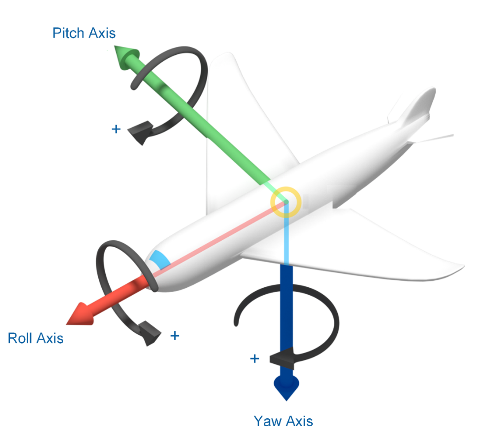
Inertial Measurement
This lab explores acceleration, rotation, and magnetic field measurements using an Inertial Measurement Unit (IMU) sensor. Designed for NI ELVIS III.

Measurement Software and Analysis
In this lab, students will complete activities in data acquisition, such as storing, analyzing and presenting data on a PC. Designed for NI ELVIS III.
Featured Lab Manuals
Communications Principles
Students study a broad range of introductory digital and analog telecommunications topics through a series of hands-on laboratory experiments. Designed for NI ELVIS III.
Digital Communications
Digital Communications by Prof. Robert Heath features deep dives into algorithm design for modulation and demodulation; pulse shaping; energy detection; equalization; frame...
Introductory Communications Systems
The twelve lab exercises presented in this package are intended to accompany an introductory course in communication systems offered at the junior or senior level in an electrical...Featured Labs
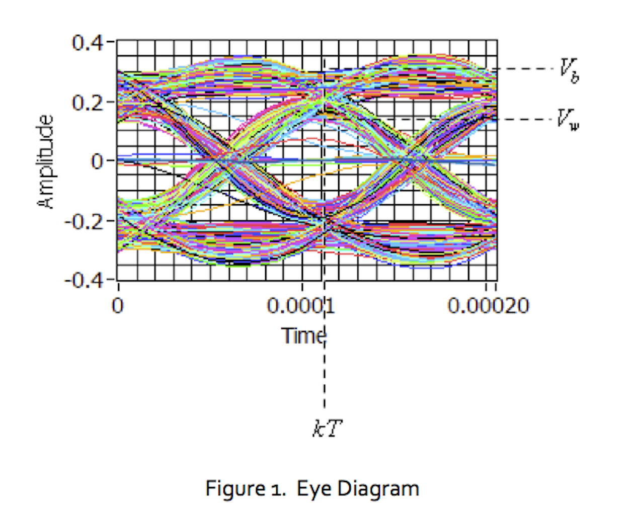
Lab 10: The Eye Diagram
In this lab project we will examine how the eye diagram changes when intersymbol interference (ISI) is present in the communication channel.

Amplitude Demodulation
In this lab students use the Emona Communication board to learn two methods for amplitude modulation (AM) and demodulation. Designed for NI ELVIS III.

Lab 12: Quadrature Phase-Shift Keying
In this lab project we introduce quadrature phase-shift keying (QPSK), a variation on binary phase-shift keying that encodes two bits of data into each symbol.