From 04:00 PM CDT – 08:00 PM CDT (09:00 PM UTC – 01:00 AM UTC) Tuesday, April 16, ni.com will undergo system upgrades that may result in temporary service interruption.
We appreciate your patience as we improve our online experience.
From 04:00 PM CDT – 08:00 PM CDT (09:00 PM UTC – 01:00 AM UTC) Tuesday, April 16, ni.com will undergo system upgrades that may result in temporary service interruption.
We appreciate your patience as we improve our online experience.
Note: This page is about NI-DAQ also known as Traditional NI-DAQ (Legacy). NI-DAQmx replaced Traditional NI-DAQ (Legacy) in 2003. NI strongly recommends using NI-DAQmx for new designs and migrating existing Traditional NI-DAQ (Legacy) applications to NI-DAQmx. Please review the Getting Started with NI-DAQmx guide for more information on migration.
This document describes how to calibrate your multifunction data acquisition (DAQ) board from NI. The boards that will be discussed are the AT-MIO E Series Plug and Play boards, the AT-MIO-64F-5, the AT-MIO-16F-5, and the AT-MIO-16X. The latter three -- AT-MIO-64F-5, the AT-MIO-16F-5, and the AT-MIO-16X -- will be referred to as legacy boards.
All of the boards mentioned can be calibrated using LabVIEW or using Traditional NI-DAQ (Legacy) with built-in software routines. These calibration routines can also be used to calibrate the boards from LabWindows/CVI, ComponentWorks, or several third-party compilers.
This document will describe general calibration information, and then will provide a step-by-step procedure for calibrating the board. You need to read only the step-by-step instructions that apply to your hardware and software configuration.
Calibration refers to a procedure of reading offset and gain errors from an MIO board and updating special onboard analog calibration circuitry that will correct these errors. All AT-MIO boards are calibrated as shipped from the factory. When the board is calibrated, the calibration constants, values used to update the analog calibration circuitry, are stored in nonvolatile memory on the board. From memory they can be loaded when needed. The offset and gain errors, however, may drift with time and temperature. As a result, the calibration constants determined at the factory may not apply to the current operating environment of the board. To achieve the specified accuracy of the board, it must be calibrated in the operating environment.
For example, let us calculate the voltage error that could occur from temperature drift alone. Consider a situation in which we are using an AT-MIO-16E-1 board calibrated at the factory at a temperature of 25° C, but is now being used at 35° C. We can find the approximate errors associated with temperature fluctuations from the temperature drift specifications provided in the user manual. The specifications of interest are the pregain, postgain, and gain offset temperature coefficients. Table 1 shows the values for these coefficients for the AT-MIO-16E-1.
|
Parameter
|
Value
|
| Pregain Offset Temperature Coefficient |
± 5 µV/°C
|
| Postgain Offset Temperature Coefficient |
± 240 µV/°C
|
| Gain Offset Temperature Coefficient (GOTC) |
± 20 ppm/°C
|
Simply multiplying the pregain and postgain offset temperature coefficients by the temperature change of 10° C gives us possible offset errors of ± 50 µV and ± 2.4 mV for the pregain and postgain respectively. To calculate the possible error caused by a change in the gain offset, we must know the approximate voltage of the signal being measured and the gain setting of the MIO board. Let us assume a unipolar input range of 10 V, a gain of 10, and an input voltage of approximately 1 V.
The gain offset is calculated as a fractional change in the gain. Multiplying the GOTC by the 10° C temperature change gives a gain offset of ± 200 ppm. Using the known gain setting of 10, the change in the gain can be calculated as ± 10(200/106) V/V, which is ± 0.002 V/V. Now, assuming an input voltage level of 1 V, the overall error which may occur can be calculated as ± 2.0 mV.
The overall error caused by temperature drift is the sum of the three calculated errors, ± 4.45 mV. While an error of this magnitude is not large when compared to 1 V, it can be highly detrimental when trying to measure voltages in the mV range.
The AT-MIO E Series boards, the AT-MIO-64F-5, the AT-MIO-16F-5, and the AT-MIO-16X boards all have nonvolatile memory, EEPROMs, used to store the calibration constants. The calibration constants are written to calibration digital-to-analog converters (CALDACs). The CALDACs output an analog voltage proportional to the calibration constants written to them. These voltages are used to modify the incoming or outgoing analog voltage path in a way which will cancel the offset and gain errors.
Depending on your board, there may be CALDACs specifically for unipolar analog input, bipolar analog input, unipolar analog output, or bipolar analog output. Consult the user manual for your board for a more detailed description of the calibration registers. In the case of E Series boards, you should consult the E Series Register-Level Programming Manual for a complete description of the calibration registers.
The EEPROMs on the boards can be used to store different sets of calibration constants. When the board is calibrated at the factory, the calibration constants are stored in a read-only portion of the EEPROM. Until the board is self calibrated by the user, these calibration constants will be the set that is written to the CALDACs upon initialization of the board. When the board is calibrated in its working environment, you have the choice to save the newly generated calibration constants to a location in the EEPROM. When this is done, these calibration constants will be written to the EEPROM as well as to the CALDACs.
Since the CALDACs do not have memory, each time the computer is powered off, the CALDACs lose their values. As a result, the calibration constants must be re-loaded each time the board is powered up and used. Traditional NI-DAQ (Legacy) automatically loads the CALDACs with the default calibration constants the first time a function is called which requires them. In the case of LabVIEW, the CALDACs are loaded when the first virtual instrument (VI) that uses data acquisition is loaded. The default calibration constants may be the factory constants, or constants saved in a user area of the EEPROM. After a calibration, if the constants are saved to the EEPROM, the newly created calibration constants become the default calibration constants. Calibration constant loading will be discussed in the section Calibration Constant Loading later in this application note. You can also use the calibration functions to change the default calibration constants. This will be discussed in a subsequent section.
Using the calibration functions you can instruct the board to perform a self calibration, or calibrate the internal reference voltage. When a calibration is performed, the board will determine the calibration constants for the analog input, or the analog output, or the internal reference voltage, and store these constants in the EEPROM. Once the self calibration is performed, the set of calibration constants that was determined will become the default calibration constants, and will be automatically loaded when any Traditional NI-DAQ (Legacy) function or LabVIEW data acquisition VI is called.
The calibration constants need to be written to the CALDACs to compensate for the pregain and postgain offset, and the gain error. During the calibration procedure, these error sources are calibrated in a specific order. Figure 1 shows the offset calibration order.
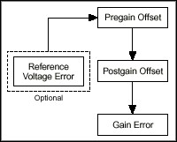
The pregain offset is the voltage difference between the true voltage and the measured voltage at the input of the amplifier. This offset is measured by grounding the inputs to the programmable gain instrumentation amplifier (PGIA). This offset is measured at different gains, and once calibrated, should be independent of the gain setting. Similarly, the postgain offset is the difference between the true and measured voltage at the output of the amplifier. This offset is measured by grounding the input of the PGIA and measuring the output. The circuitry is adjusted until this output is as small as possible.
The gain error is the difference between the gain setting and the measured gain. This is calibrated by measuring the internal reference voltage at a gain of 1, and adjusting the gain until the measured voltage is equal to the value of the reference voltage stored in the EEPROM. Figure 1 shows that the gain error is always calibrated after the postgain offset, which in turn is always calibrated after the pregain offset. The pregain and postgain offsets and the gain error are all adjusted using the CALDACs on the board. Each CALDAC must be loaded with a value that will minimize the errors caused by these sources. These values, which update the CALDACs to minimize the errors are the calibration constants.
There is a final error source, the difference between the internally stored reference voltage and its actual value. The calibration functions can be used to adjust this parameter as well. However, to calibrate this voltage, you need a high-precision voltage source.
Using the calibration functions provided with Traditional NI-DAQ (Legacy) and LabVIEW, there are three operations you can perform. You can 1) calibrate the analog circuitry, 2) change the default load area, and 3) calibrate the internal reference voltage. For the AT-MIO-16X, the AT-MIO-16F-5, and the AT-MIO-64F-5, you must specify whether you are performing an analog input or an analog output calibration when calibrating the analog circuitry. For the E Series boards, the self-calibration procedure calibrates both the analog input and output portions of the analog circuitry. For a complete description of how these functions are used, see the sections entitled Calibrating Your E Series Board and Calibrating Your Legacy Board.
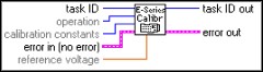
The functions used to calibrate the E Series boards are called E Series Calibrate and Calibrate_E_Series, for LabVIEW and Traditional NI-DAQ (Legacy), respectively. Figure 2 shows the terminal connections for the E Series Calibrate VI.
The function prototype for the Calibrate_E_Series function is:
status = Calibrate_E_Series (deviceNumber, CalOP, setOfCalConst, CalRefVolts)
The LabVIEW E Series Calibrate VI
The E Series Calibrate VI can be used alone to perform a one-time calibration, or it can be used in an application VI to perform routine calibrations. The input task ID can be a task ID created by any of the configuration VIs, such as AI Configure, or it can be the device number of the device you wish to calibrate. You can find the device number for your board by opening the Traditional NI-DAQ (Legacy) configuration utility and locating the number beside the device of interest in the device list.
The operation input to the VI specifies which type of operation you wish to perform. The calibration constants input determines which calibration constants you wish to use, or where you wish to save the newly created calibration constants. Table 2 and Table 3 show a list of the possible values for operation and calibration constants and the description of each.
|
operation Input
|
Description
|
|
0
| No change (default input). |
|
1
| Set default load area (default setting). |
|
2
| Perform a self-calibration. |
|
3
| Perform an external calibration. |
|
calibration constants Input
|
Description
|
|
0
| No change (default input). |
|
1
| Factory EEPROM area (default setting). |
|
2
| NI-DAQ software area. |
|
3
| User EEPROM area. |
The reference voltage input indicates the voltage of the external voltage supply you are using to perform an external calibration. When performing an external calibration, you must use a high-precision voltage supply. This will be discussed further in the section entitled Using the E Series Calibrate VI to Perform an External Calibration.
The error input or output describes error conditions before or after the execution of the VI. If you are using the E Series Calibrate VI as a stand-alone VI, you do not need to use the error in input. When using the VI inside of an application to perform routine calibrations, you can use the task ID and the error in to sequence your VIs. For more information, see the LabVIEW Data Acquisition Basics Manual.
The NI-DAQ Calibrate_E_Series Function
For the Calibrate_E_Series function, deviceNumber is the number of the board that you want to calibrate. This number can be found by looking in the Traditional NI-DAQ (Legacy) Configuration Utility and finding the number in the device list next to the board of interest. CalOP is the parameter that determines which operation you wish to perform. Table 4 shows the possible values calOP can assume.
|
calOP Value
|
Operation Performed
|
| ND_SET_DEFAULT_LOAD_AREA | Make setOfCalConst the default load area. |
| ND_SELF_CALIBRATE | Perform self-calibration of the device. |
| ND_EXTERNAL_CALIBRATE | Perform an external calibration of the device. |
SetOfCalConst selects the set of calibration constants used to load the CALDACs. These calibration constants are either stored in the EEPROM, or are contained in software by Traditional NI-DAQ (Legacy). Table 5 shows possible values you can use for setOfCalConst.
|
setOfCalConst Value
|
Description
|
| ND_FACTORY_EEPROM_AREA | Factory calibration area of the EEPROM. This area is read-only. |
| ND_NI_DAQ_SW_AREA | NI-DAQ maintains calibration constants. No writing of the EEPROM takes place. |
| ND_USER_EEPROM_AREA | User calibration area of the EEPROM. The new calibration constants will be written here. |
Note that the values that you pass for setOfCalConst and calOP are constant definitions defined in header files. The particular header file depends upon the compiler or development environment you are using. Consult the Traditional NI-DAQ (Legacy) User Manual for information regarding specific compilers. If you are using LabWindows/CVI, the constants are defined in the DATAACQ.H file.
CalRefVolts is the DC calibration voltage that you will connect to the board to calibrate the internal reference voltage. This voltage must come from a high-precision voltage source. Calibration of the internal reference voltage will be discussed in the section entitled Using Calibrate_E_Series to Calibrate the Internal Reference Voltage.
Performing a Self-Calibration on Your E Series Board
Once the board is in its operating environment, frequent calibration ensures the most accurate, stable, and repeatable measurements. A self-calibration is the most effective way to do this. During a self-calibration, both the analog inputs and the analog outputs are calibrated. The internal reference voltage is not calibrated during a self-calibration.
A self-calibration will create a new set of calibration constants by performing a pregain offset, a postgain offset, and a gain error calibration, as seen in Figure 1. Once the calibration is performed, the new calibration constants are loaded to the CALDACs on the board. If you wish, these calibration constants can be saved to the EEPROM, where they can be reloaded when necessary. It is important to save the calibration constants if they will be needed after the board has been powered down. If the calibration constants are not saved to the EEPROM, they will be lost when the computer is powered down.
Steps for Performing a Self-Calibration in LabVIEW
The following are the steps for performing a self-calibration of your E Series board using the E Series Calibrate VI in LabVIEW.
Step 1- Set the operation input to 2, which is self calibrate.
Step 2- If you wish to save the new calibration constants to the EEPROM, set calibration constants to 3, which is the user EEPROM area. Once in the user EEPROM area, you can load the constants when needed. If you need the calibration constants only for the time that the computer will be powered, set calibration constants to 2, which is the Traditional NI-DAQ (Legacy) software area. With this setting, Traditional NI-DAQ (Legacy) will maintain the calibration constants until another calibrations performed, or the computer is powered down. When operation is set to 2, you cannot set calibration constants to 1, which is the factory EEPROM area, because this area is read-only. If you use this setting, the VI will return an error.
The input reference voltage is ignored when operation is set to 2.
When performing a self-calibration, no external connections need to be made to the board. Self-calibrations can be performed as often as desired. Frequent calibrations in no way harm the board, and produce the most stable and accurate results.
Steps for Performing a Self-Calibration with Traditional NI-DAQ (Legacy)
The following are the steps for performing a self-calibration of your E Series board with the Calibrate_E_Series function in Traditional NI-DAQ (Legacy).
Step 1- Set the calOP value to ND_SELF_CALIBRATE.
Step 2- If you wish to save the new calibration constants to the EEPROM, set setOfCalConst to ND_USER_EEPROM_AREA. If you need the calibration constants only for the time that the computer will be powered, set setOfCalConst to ND_NI_DAQ_SW_AREA. When calOP is set to ND_SELF_CALIBRATE, you cannot set setOfCalConst to ND_FACTORY_EEPROM_AREA, because this area is read-only. If you use this setting, the function will return an error.
The parameter calRefVolts is ignored when calOP is set to ND_SELF_CALIBRATE. The final function call will look like:
status = Calibrate_E_Series (deviceNumber, ND_SELF_CALIBRATE, ND_USER_EEPROM_AREA, CalRefVolts)
When performing a self-calibration on the E Series boards, no external connections to the board need be made. Self-calibrations can be performed as often as desired. Frequent calibrations in no way harm the board, and produce the most stable and accurate results.
Performing an External Calibration of Your E Series Board
Occasionally it is necessary to perform an external calibration in which the internal reference voltage of the board is calibrated against a known source. During an external calibration of the E Series boards, the analog inputs and outputs are calibrated as well. When performing an external calibration, it is necessary to use a high-precision voltage source. The source must be more accurate than the analog-to-digital converter on the board. When calibrating a 12-bit board, your source should be at least 50 ppm (0.005%) accurate. When calibrating a 16-bit board, your source should be at least 10 ppm (0.001%) accurate. For example, when supplying an external 10 V (i.e., full scale) calibration voltage to a 12-bit board, the source must be accurate to within 500 µV. However, when supplying the same signal to a 16-bit board, the source must be accurate to within 100 µV.
Connecting the High-Precision Voltage Source
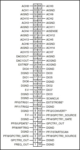
When performing an external calibration, you must connect an external reference voltage to the board. The connections are slightly different for 16-bit boards than for 12-bit boards. Table 6 describes the connections that must be made for each type of E Series board, and Figure 3 shows the 68-pin I/O connector.
|
12-Bit E Series Devices
|
16-Bit E Series Devices
|
| 1. Connect the positive output of the reference voltage source to the analog input channel 8. | 1. Connect the positive output of your reference voltage source to analog input channel 0. |
| 2. Connect the negative output of your reference voltage source to the AISENSE line. | 2. Connect the negative output of your reference voltage source to analog input channel 8. |
| 3. Connect the DAC0 line to analog input channel 0. | 3. If your reference voltage source and your computer are floating with respect to each other, connect the negative output of your reference voltage source to the AIGND line as well as to analog input channel 8. |
| 4. If your reference voltage source and your computer are floating with respect to each other, connect the AISENSE line to the AIGND line as well as to the negative output of your reference voltage source. |
Steps for Performing an External Calibration in LabVIEW
The following are the steps for performing an external calibration of your E Series board using the E Series Calibrate VI of LabVIEW.
Step 1- Set the operation input to 3, which is external calibrate.
Step 2- If you wish to save the new calibration constants to the EEPROM, set calibration constants to 3, which is the user EEPROM area. If you need the calibration constants only for the time that the computer will be powered on, set calibration constants to 2, which is the Traditional NI-DAQ (Legacy) software area. When operation is set to external calibrate, you cannot set calibration constants to the factory EEPROM area, because this area is read-only. If you use this setting, the function will return an error.
Step 3- The input reference voltage is the value of the external voltage that you will apply to the board. Remember that this voltage is supplied by a high-precision voltage supply.
Steps for Performing an External Calibration with Traditional NI-DAQ (Legacy)
The following are the steps for performing an external calibration of your E Series board using the Calibrate_E_Series function of Traditional NI-DAQ (Legacy).
Step 1- Set the calOP value to ND_EXTERNAL_CALIBRATE.
Step 2- If you wish to save the new calibration constants to the EEPROM, set setOfCalConst to ND_USER_EEPROM_AREA. If you need the calibration constants only for the time that the computer will be powered on, set setOfCalConst to ND_NI_DAQ_SW_AREA. When calOP is set to ND_EXTERNAL_CALIBRATE, you cannot set setOfCalConst to ND_FACTORY_EEPROM_AREA, because this area is read-only. If you use this setting, the function will return an error.
Step 3- The parameter calRefVolts is the value of the external voltage that you will apply to the board. Remember that this voltage is supplied by a high-precision voltage supply.
The function call to Traditional NI-DAQ (Legacy) will look like the following:
status = Calibrate_E_Series (deviceNumber, ND_EXTERNAL_CALIBRATE, ND_USER_EEPROM_AREA, CalRefVolts)
Changing the Default Calibration Constants of Your E Series Board
Once a calibration has been performed, and the calibration constants have been saved, there are two sets of usable calibration constants in the EEPROM. One is the set created at the factory, and the other is the set created by the user calibration. It is possible to calibrate the board again, and maintain a set of calibration constants in Traditional NI-DAQ (Legacy) software. Any set of constants maintained in Traditional NI-DAQ (Legacy) will be lost when the computer is powered down.
Occasionally it may be desirable to change the calibration constants being used by the board. For example, you may have one set of calibration constants that are used when the board is in a high-temperature environment, and the factory constants that are used at room temperature. You can change the calibration constants used with the calibration functions provided by LabVIEW and Traditional NI-DAQ (Legacy). Once the calibration constants are changed, the new set of calibrations constants become the default constants. The default constants are automatically loaded when the board is initialized.
Using the E Series Calibrate VI to Change the Default Calibration Constants
The following are the steps for changing the default calibration constants on your E Series board using LabVIEW.
Step 1- Set the operation input to 1, which is set default load area.
Step 2- Set the calibration constants input to the area that you wish to become the default load constants. Values of 1, 2, or 3 are all valid.
For more information on the loading of the calibration constants, see the section entitled Calibration Constant Loading.
Using the Calibrate_E_Series Function to Change the Default Calibration Constants
The following are the steps for changing the default calibration constants on your E Series board using Traditional NI-DAQ (Legacy).
Step 1- Set the calOP parameter to ND_SET_DEFAULT_LOAD_AREA.
Step 2- Set the setOfCalConst parameter to the area that you wish to become the default load constants. Values of ND_FACTORY_EEPROM_AREA, ND_NI_DAQ_SW_AREA, and ND_USER_EEPROM_AREA, are all valid.
The section entitled Calibration Constant Loading further discusses how the calibration constants are loaded.
Calibrating Your Legacy Board
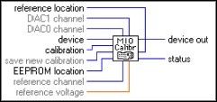
The VI used to calibrate your AT-MIO-64F-5, AT-MIO-16F-5, or AT-MIO-16X in LabVIEW is the MIO Calibrate VI. Traditional NI-DAQ (Legacy) uses the function MIO_Calibrate to calibrate the boards. Figure 4 shows the terminal connections for the MIO Calibrate VI.
The function prototype for the MIO_Calibrate function is:
status = MIO_Calibrate (deviceNumber, calOP, saveNewCal, EEPROMloc, calRefChan, DAC0chan, DAC1chan, calRefVolts, refLoc)
The MIO Calibrate VI can be used as a stand-alone VI, or it can be sequenced with other data acquisition VIs to perform regular calibrations within an application VI. For the MIO Calibrate VI, device is the number of the device which you wish to calibrate. The input calibration determines which operation you wish to perform. Table 7 shows the different calibration operations performed by the MIO Calibrate VI.
Table 7. The Calibration Operations Performed by the MIO Calibrate VI, and the Corresponding calibration Value
calibration Input
| Calibration Operation
|
0
| Reserved. |
1
| Load calibration contants from the EEPROM location. |
2
| Calibrate the ADC using the internal reference voltage calibration constants in reference location. |
3
| Calibrate the DACs using the internal voltage calibration constants in reference location. |
4
| Calibrate the internal reference voltage. You must connect a DC voltage specified by reference voltage to the analog input channel reference channel. The new calibration constants are stored in reference location. |
5
| Copy the ADC calibration constants from EEPROM location to the EEPROM load area. |
6
| Copy the DAC calibration constants from EEPROM location to the EEPROM load area. |
The input save new calibration determines whether the new calibration constants are saved to the EEPROM. The value of EEPROM location and reference location determine where the new calibration constants are saved. When the ADC or the DACs are calibrated, the calibration constants for the operation are saved in the EEPROM location. When the internal reference voltage is calibrated, the calibration constants are saved in the reference location. The other parameters, reference channel, DAC0 channel, DAC1 channel, and reference voltage, are used only during certain calibration procedures. These parameters will be discussed during the step-by-step procedures in the following sections. Table 8 shows the valid values of EEPROM location, and Table 9 shows the values of reference location.
Input
| EEPROM Location
|
0
| Reserved |
1
| User calibration area 1 (default setting) |
2
| User calibration area 2 |
3
| User calibration area 3 |
4
| User calibration area 4 |
5
| User calibration area 5 (load area for AT-MIO-16F-5) |
6
| User calibration area 6 (AT-MIO-16X and AT-MIO-64F-5 only) |
7
| User calibration area 7 (AT-MIO-16X and AT-MIO-64F-5 only) |
8
| Load area for AT-MIO-16X and AT-MIO-64F-5 |
9
| Factory calibration area for unipolar (AT-MIO-16X and AT-MIO-64F-5 only) |
10
| Factory calibration area for bipolar (AT-MIO-16X andAT-MIO-64F-5 only) |
11
| Factory calibration area for AT-MIO-16F-5 |
Input
| reference location
|
0
| Reserved. |
1
| User reference area 1 (default setting) |
2
| User reference area 2 |
3
| User reference area 3 (AT-MIO-16X and AT-MIO-64F-5 only) |
4
| User reference area 4 (AT-MIO-16X and AT-MIO-64F-5 only) |
5
| Reserved |
6
| Factory reference area (cannot write to this area) |
The Traditional NI-DAQ (Legacy) MIO_Calibrate Function
For the MIO_Calibrate function, deviceNumber is the number of the device you wish to calibrate. The parameter calOP determines which operation you wish to perform. Table 10 shows the different calibration operations performed by the MIO_Calibrate function.
calOP Value
| Calibration Operation
|
1
| Load calibration constants from EEPROMloc. |
2
| Calibrate the ADC using the internal reference voltage calibration constants in refLoc. |
3
| Calibrate the DACs using the internal voltage calibration constants in refLoc. |
4
| Calibrate the internal reference voltage. You must connect a DC voltage of calRefVolts to the analog input channel calRefChan. The new calibration constants are stored in refLoc. |
5
| Copy the ADC calibration constants from EEPROMloc to the EEPROM load area. |
6
| Copy the DAC calibration constants from EEPROMloc to the EEPROM load area. |
The value of saveNewCal determines whether the new calibration constants are saved to the EEPROM. The value of EEPROMloc and refLoc determine where the new calibration constants are saved. When calibrating the ADC or the DACs, the calibration constants are saved in EEPROMloc. When calibrating the internal reference voltage, the calibration constants are saved in refLoc. The other parameters calRefChan, DAC0chan, DAC1chan, and, calRefVolts, are used only during certain calibration procedures. These parameters will be discussed during the step-by-step procedures in the following sections. Tables 11a and 11b show the valid values of EEPROMloc, and Table 12 shows the values of refLoc.
Input
| EEPROMloc for AT-MIO-16F-5
|
1
| User calibration area 1 |
2
| User calibration area 2 |
3
| User calibration area 3 |
4
| User calibration area 4 |
5
| User calibration area 5 (initial load area) |
6
| Factory calibration area (cannot write to this area) |
Input
| EEPROMloc for AT-MIO-64F-5 and16X
|
1
| User calibration area 1 |
2
| User calibration area 2 |
3
| User calibration area 3 |
4
| User calibration area 4 |
5
| User calibration area 5 |
6
| User calibration area 6 |
7
| User calibration area 7 |
8
| User calibration area 8 (initial load area) |
9
| Factory calibration area for unipolar (cannot write to this area) |
10
| Factory calibration area for bipolar (cannot write to this area) |
| Input | refLoc |
1
| User reference area 1 (default setting) |
2
| User reference area 2 |
3
| User reference area 3 (AT-MIO-16X and AT-MIO-64F-5 only) |
4
| User reference area 4 (AT-MIO-16X and AT-MIO-64F-5 only) |
5
| Reserved |
6
| Factory reference area (cannot write to this area) |
Performing a Self-Calibration of the Analog Inputs of Your Legacy MIO Board
Once the board is in its operating environment, frequent calibrations ensure the most accurate and stable analog measurements. For legacy boards, this is most effectively achieved by calibrating the analog inputs (ADC calibration). The legacy boards calibrate the analog inputs and the analog outputs separately. A separate call to the calibration function must be made to calibrate each operation.
Once calibrated, the calibration constants are written to the CALDACs to compensate for the offsets and gain errors. In addition, these calibration constants may be saved to the EEPROM to be used at a later time. If the calibration constants are not saved, they will be lost when the computer is powered off.
Steps for Performing a Calibration of the Analog Inputs with LabVIEW
The steps for calibrating the analog inputs of your legacy MIO board with LabVIEW are as follows.
Step 1- Set the device value to the number of the device you wish to calibrate.
Step 2- Set the calibration value to 2, which is to calibrate the ADC.
Step 3- If you wish to save the new calibration constants to the EEPROM, set save new calibration to a value of 1. If you need the calibration constants only for the time that the computer will be powered on, set save new calibration to 0. If you do not save the calibration constants, they will be lost when the computer is powered off, or when another calibration is performed.
Step 4- Set EEPROM location to the area in which you wish to save the newly created calibration constants (1-4, 6, 7). When calibrating the analog inputs, you cannot set EEPROM location to the factory calibration area, because this area is read-only. An error will occur if this setting is used.
Step 5- Set reference location to 6 if you want to use the factory reference voltage. Set it to one of the user reference areas (1-4) if you have already performed a calibration of the internal reference voltage and wish to use the saved calibration constants from that calibration.
The inputs DAC0 channel, DAC1 channel, reference channel, and reference voltage are all ignored when calibration is set to 2. No external connections are necessary when performing a calibration of the analog inputs.
Steps for Performing a Calibration of the Analog Inputs with Traditional NI-DAQ (Legacy)
The following are the steps for calibrating the analog inputs of your legacy MIO board using the Traditional NI-DAQ (Legacy) library.
Step 1- Set the calOP value to 2.
Step 2- If you wish to save the new calibration constants to the EEPROM, set saveNewCal to a value of 1. If you need the calibration constants only for the time that the computer will be powered on, set saveNewCal to 0. If you do not save the calibration constants, they will be lost when the computer is powered off, or when another calibration is performed.
Step 3- Set EEPROMloc to the area in which you wish to save the newly created calibration constants. When calibrating the analog inputs, you cannot set EEPROMloc to the factory calibration area, because this area is read-only. An error will occur if this setting is used.
Step 4 - Set refLoc to 6 if you want to use the factory reference voltage. Set it to one of the user reference areas if you have already performed a calibration of the internal reference voltage and wish to use the saved calibration constants from that calibration.
The parameters calRefChan, DAC0chan, DAC1chan, and calRefVolts, are all ignored when calOP is set to 2.
No external connections are necessary when performing a calibration of the analog inputs. In general, the final function call is as follows:
status = MIO_Calibrate (deviceNumber, 2, 1, EEPROMloc, calRefChan, DAC0chan, DAC1chan, calRefVolts, 6)
Performing a Self-Calibration of the Analog Outputs of Your Legacy MIO Board
Similar to analog inputs, the legacy boards produce the most stable analog outputs when they are calibrated in their operating environment. The calibration constants for the analog output calibration are stored in an area of the EEPROM separate from the calibration constants for the analog input calibration. It is not necessary to calibrate both the analog inputs and the analog outputs. Simply calibrate the circuitry of the operation you wish to perform.
Connections to Make Before Calibrating Analog Outputs
When you are using the AT-MIO-16X or the AT-MIO-16F-5, you must make external connections to calibrate the analog outputs. For the AT-MIO-16X, you must connect DAC0 or DAC1 to the positive side of the differential analog input channel specified by DAC0 channel or DAC1 channel. You must then connect the AOGND pin to the negative side of the differential analog input channel. When calibrating the AT-MIO-16F-5 you must connect DAC0 or DAC1 to the negative side of the differential analog input specified by DAC0 channel or DAC1 channel. The AOGND pin must be connected to the positive side of the analog input. If these connections are not made correctly, the calibration will not converge, and an error will result.
Steps for Performing a Calibration of the Analog Outputs with LabVIEW
The following steps can be used when performing a calibration of the analog outputs of your legacy MIO board using LabVIEW.
Step 1- Set the calibration value to 3.
Step 2- If you wish to save the new calibration constants to the EEPROM, set save new calibration to a value of 1. If you need the calibration constants only for the time that the computer will be powered on, set save new calibration to 0. If you do not save the calibration constants, they will be lost when the computer is powered off, or when another calibration is performed.
Step 3- Set EEPROM location to the area in which you wish to save the newly created calibration constants. When calibrating the analog outputs, you cannot set EEPROM location to the factory calibration area, because this area is read-only. An error will occur if this setting is used.
Step 4- When calibrating the analog outputs, you must connect either of the analog outputs, DAC0 and DAC1, to an analog input channel. The channels which these outputs are connected to must be passed as
DAC0 channel and DAC1 channel respectively. If you are using an AT-MIO-64F-5, these parameters are ignored because DAC0 is internally routed to an input channel.
Step 5- Set reference location to 6 if you want to use the factory reference voltage. Set it to one of the user reference areas if you have already performed a calibration of the internal reference voltage and wish to use the saved calibration constants from that calibration.
When calibration is set to 3, the parameters reference channel and reference location are ignored.
Steps for Performing a Calibration of the Analog Outputs with Traditional NI-DAQ (Legacy)
To calibrate the analog outputs of your legacy MIO board using Traditional NI-DAQ (Legacy), follow these steps.
Step 1- Set the calOP value to 3.
Step 2- If you wish to save the new calibration constants to the EEPROM, set saveNewCal to a value of 1. If you need the calibration constants only for the time that the computer will be powered on, set saveNewCal to 0. If you do not save the calibration constants, they will be lost when the computer is powered off, or when another calibration is performed.
Step 3- Set EEPROMloc to the area in which you wish to save the newly created calibration constants. When calibrating the analog inputs, you cannot set EEPROMloc to the factory calibration area, because this area is read-only. An error will occur if this setting is used.
Step 4- When calibrating the analog outputs, you must connect either of the outputs, DAC0 and DAC1, to an analog input channel. The channels which these outputs are connected to must be passed as
DAC0chan and DAC1chan respectively. If you are using an AT-MIO-64F-5, these parameters are ignored, because DAC0 is internally routed to an input channel.
Step 5- Set refLoc to 6 if you want to use the factory reference voltage. Set it to one of the user reference areas if you have already performed a calibration of the internal reference voltage and wish to use the saved calibration constants from that calibration.
When calOP is set to 3, the parameters calRefChan and calRefVolts are ignored.
Performing an External Calibration of Your Legacy MIO Board
Occasionally it is necessary to calibrate the internal reference voltage of your board. This is the voltage that is used as a known reference when calibrating the analog input voltages or generating the analog output voltages. You should calibrate the internal reference voltage if it has not been calibrated for more than a year, or if the board will be used at extreme temperatures. However, you can also calibrate the internal reference voltage as often as needed to satisfy calibration documentation requirements.
When calibrating the internal reference voltage, it is important to use a high-precision voltage supply. The voltage supply must have an accuracy greater than the accuracy of the analog-to-digital converter of the MIO board. The required precision of the source depends on the accuracy of the board you are calibrating. If you have a 16-bit board, then the accuracy of the source should be 10 ppm, and for a 12-bit board it should be 50 ppm. If your source is not accurate enough, you will receive an error message during calibration, and the calibration will not converge.
Connecting the High-Precision Voltage Source
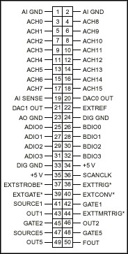
When calibrating the internal reference voltage, you must connect the high-precision voltage source to the board. This is done by connecting the positive lead of the supply to the positive side of the analog input channel specified by reference channel, and the negative lead of the supply to the negative side of the input channel. Figure 5 provides the pinouts for the legacy boards.
Steps for Performing a Calibration of the Reference Voltage with LabVIEW
The following steps can be used to calibrate the internal reference voltage of your legacy MIO board using LabVIEW.
Step 1- Set the calibration value to 4.
Step 2- The parameter reference channel is the analog input channel that the calibration voltage is connected to. This is the voltage from the high-precision voltage supply.
Step 3- Set reference voltage to the value of the DC calibration voltage connected to reference channel.
Step 4- To save the calibration constants, set reference location to one of the user reference areas.
The parameters EEPROM location, DAC0 channel, and DAC1 channel are ignored when calibration is set to 4.
Steps for Performing a Calibration of the Reference Voltage with Traditional NI-DAQ (Legacy)
The procedure for calibrating the internal reference voltage of your MIO legacy board with Traditional NI-DAQ (Legacy) is as follows:
Step 1- Set the calOP value to 4.
Step 2- The parameter calRefChan is the analog input channel that the calibration voltage is connected to. This is the voltage from the high-precision voltage supply.
Step 3- Set calRefVolts to the value of the DC calibration voltage connected to calRefChan.
Step 4- To save the calibration constants, set refLoc to one of the user reference areas.
The parameters EEPROMloc, DAC0chan, and DAC1chan are ignored when calOP is set to 4.
When calibrating the internal reference voltage, you must connect the high-precision voltage source to the board. This is done by connecting the positive lead of the supply to the positive side of the analog input channel specified by calRefChan, and the negative lead of the supply to the negative side of the input channel.
Performing a Complete Calibration of Your Legacy MIO Board
If you wish to perform a complete calibration of your legacy board, you must call the calibration routine three times. You must first calibrate the internal reference voltage as discussed above, and then calibrate the analog input and the analog output. The order of calibrating the input and the output does not matter, but the internal reference voltage must be calibrated first. This applies regardless of whether you are using LabVIEW or Traditional NI-DAQ (Legacy).
Calibration Constant Loading
The E Series boards and the legacy boards discussed in this application note do not have memory for the CALDACs. As a result, the calibration constants written to the CALDACs are lost when the board is powered down. Each time the board is used, it is initialized. During the initialization procedure, the default calibration constants are written to the CALDACs. When using LabVIEW, this initialization procedure occurs the first time a data acquisition VI is called. When using LabWindows/CVI or a third-party compiler and Traditional NI-DAQ (Legacy), the calibration constants are loaded when the first call to Traditional NI-DAQ (Legacy) that requires them to be loaded is made.
For E Series devices, you can use the calibration functions to specify the default load area. The default load area should be the factory EEPROM area or the user EEPROM area. Once the default load area is set, the calibration constants in that area will be the one written to the CALDACs. This remains true even if the computer is powered down and then restarted. When you calibrate the board and specify an EEPROM location in which to save the new calibration constants, that EEPROM location automatically becomes the default load area. If the Traditional NI-DAQ (Legacy) software area is chosen as the default-load area, then the computer is powered down, upon restarting the computer, the factory EEPROM area will become the default load area. Remember that calibration constants saved in the Traditional NI-DAQ (Legacy) software area are lost when the computer is powered down.
For legacy boards, there is specific area in the EEPROM that is the default-load area. Any calibration constants you save in that area will become the default calibration constants upon board initialization. With the calibration functions, you can copy constants from one area of the EEPROM to another.
NIST-Traceable Calibration Certificate
You can obtain a NIST-traceable calibration certificate from NI with your E Series board. To do this, simply contact NI and request to send your board in for recalibration, including a certificate.
1. How often should I calibrate my board?
You should perform an internal calibration as often as possible, i.e., once a day or before each measurement set in order to ensure maximum accuracy. You should perform an external calibration if the onboard reference has not been calibrated for more than a year. Also, if the board is operating in an environment more than 10½° C different from its last calibration environment, and the estimated drift due to temperature is unacceptable for your application, then you should perform an external calibration. Of course you can perform external calibrations as often as required to meet any calibration documentation requirements.
2. What voltage should I apply for an external calibration?
Typical values are between 5.00 and 9.99 V for a calibration at a gain of 1.
3. How can I get a calibration certificate?
You can return the board to NI and request recalibration with a certificate.
4. How accurate must my external source be?
The source must be more accurate than the analog-to-digital converter on the board. When calibrating a 12-bit board, your source should be at least 50 ppm (0.005%) accurate. When calibrating a 16-bit board, your source should be at least 10 ppm (0.001%) accurate. For example, when supplying an external 10 V (i.e., full scale) calibration voltage to a 12-bit board, the source must be accurate to within 500 µV. However, when supplying the same signal to a 16-bit board, the source must be accurate to within 100 µV.
5. What is the benefit of doing on-site calibration?
The benefit of doing an on-site internal calibration is that you remove any gain and offset errors from the analog circuitry. The benefit of doing an on-site external calibration is that you remove any reference drift from the analog circuitry.
6. Does my board have to be set up in differential mode?
The VIs and Traditional NI-DAQ (Legacy) functions take control of the board during the calibration procedure, so it does not matter what measurement mode is being used. In other words, the precalibration settings could be anything. The post-calibration settings are not necessarily returned to the precal settings; so it is left up to the user to set them appropriately once the calibration is complete.
7. What if I want to calibrate only analog output?
The E Series software calibrates both analog input and output at the same time, while the legacy MIO software requires individual calls for analog input or output.
8. What if I get errors during calibration?
-10401 Unknown Device: This means that the device number specified is not defined in the Traditional NI-DAQ (Legacy)
Configuration Utility.
-10403 Device Support Error: This means that the action specified is not supported for the device; for example, trying to do an E Series calibration on a legacy board.
-10801 Calibration Error: This can mean that the board EEPROM needs to be repaired.
-10842 Hardware Error: The call was appropriate for the device, but the response from the device is not consistent with the device functionality. Repeated errors of this type can mean something on the board is physically damaged.
LabVIEW and Traditional NI-DAQ (Legacy) include functions that calibrate your E Series board and certain legacy boards. With these functions you can calibrate the analog inputs, the analog outputs, and the internal reference voltage. These functions generate calibration constants that are used to update CALDACs. The CALDACs output an analog voltage that will compensate for offset and gain errors. These calibration constants can be saved in nonvolatile memory to be recalled when necessary.
In general, routine calibration of the analog inputs and analog outputs produce the most accurate and stable results. These calibrations can be performed periodically, or can be made part of your application for calibrating on a regular basis.
The internal reference voltage should be calibrated if the board is to be used in extreme temperatures, or if it has not been calibrated for more than a year. A high-precision voltage supply is necessary when calibrating the internal reference voltage.