Sensors for Condition Monitoring
Overview
Measurement Technologies and Sensors for Condition Monitoring Applications
Many sensors detect changes in equipment components. Vibration sensors are the most commonly used sensors when monitoring rotating machinery. They are often credited for sensing the mechanical degradation of equipment components two months or so in advance of a failure, as shown in Figure 1.
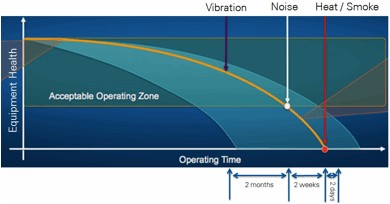
Figure 1. Asset degradation can be detected in advance by using sensors.
Other sensing technologies used in equipment condition monitoring as shown in Figure 2 include motor current, oil analysis, thermography, dynamic pressures, and operating state sensors such as speed.
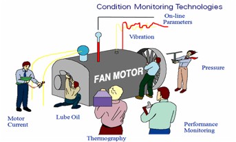
Figure 2. A variety of condition monitoring technologies help asset specialists understand asset health.
Table 1 lists the types of sensors and sample vendors used in condition monitoring.
| Measurement | Sensor | Frequency Range | Possible Signal Conditioning Needs | Vendors |
| Vibration | Accelerometer | >100 Hz |
IEPE AC/DC coupling ±24 V input or AC couple Anti-alias filter |
IMI Sensors Connection Technology Corporation Endevco/Wilcoxon |
| Vibration | Velocity | >20 Hz to <2 kHz |
IEPE AC/DC coupling ±24 V input or AC couple Anti-alias filter |
IMI Sensors Connection Technology Corporation Endevco/Wilcoxon |
| Vibration | Proximity Probe (Displacement) | <300 Hz |
Modulator/demodulator Anti-alias filter ±30 V input range | Connection Technology Corporation |
| Speed | Proximity Probe | <300 Hz |
Modulator/demodulator Anti-alias filter ±30 V input range | Connection Technology Corporation |
| Speed | Magnetic Zero Speed | Up to 15 kHz |
24 V DC power ±20 V |
Honeywell SPECTEC |
| Motor Current |
Current Shunt Current Clamp | Up to 50 kHz | ±333 mV or ±5 V | Magnelab |
| Temperature |
RTD Thermocouple | Up to 10 Hz | Noise rejection, excitation, cold-junction compensation | NI |
| Temperature | Infrared Camera | Multiple frames per sec | GigE Vision over EtherNet connection | FLIR Systems |
| Pressure | Dynamic Pressure | >100 Hz |
AC/DC coupling IEPE (some models) ±24 V or AC coupling Anti-aliasing filter |
Endevco PCB Kulite Kistler |
|
Oil Quality Oil Particulate |
Viscosity Contamination Particulates | Up to 10 Hz |
mA current input ±10 V input 50/60 Hz noise rejection |
Kittiwake Honeywell HYDAC Poseidon Systems |
| High-Frequency “Noise” | Ultrasonic | >20 kHz |
AC/DC coupling ±24 V input range Anti-aliasing filter | UE Systems |
Table 1. There are a variety of measurements, signal condition needs, and vendors for condition monitoring sensors.
Figure 3 shows a typical sensor and a sample failure mode of an asset the sensor monitors.
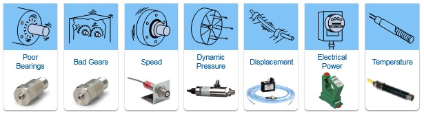
Figure 3. Typical sensors and failure modes that can be detected.
Each sensor offers the ability to monitor the degradation of mechanical and electrical components within rotating machine equipment.
Once you have identified equipment, failure modes, and sensors, the next step is to choose measurement hardware to digitize the sensors. Your choice of measurement hardware depends on your sensor characteristics including frequency range, voltage range, and signal conditioning needs.
With respect to frequency range, you can choose from two types of sensors: static and dynamic. Dynamic sensors measure frequency ranges well above 2 Hz. For example, a typical accelerometer has a frequency range of 1 Hz or 2 Hz to 15 kHz or 20 kHz. The ultrasonic sensor frequency range extends to 100 kHz or more, with a heterodyne output ranging from a few hundred hertz to 40 kHz. On the contrary, static sensors convert the monitored physical property into an electrical signal at rates of 1 Hz to 10 Hz or 20 Hz.
The other two sensor characteristics are voltage range and signal conditioning needs. Some sensors produce a voltage as high as 30 V, while others might produce only a few millivolts. Some sensors need sensor power such as IEPE power, while others might need cold-junction compensation. Table 1 lists the common signal conditioning needs for each measurement and sensor.
NI provides a wide range of hardware to acquire data from these sensors as well as the software to process and analyze the data. For deployment-ready software that connects to these sensors, please see the link below.