G.R.A.S. Selection Guide for Microphones and Preamplifiers
Overview
Contents
- Microphones
- Preamplifiers
- Microphone Sets
- Special Microphones
- Available G.R.A.S. Microphones at National Instruments
Microphones
Measurement microphones can be divided into three groups: Free-field, Pressure, and Random-incidence. The differences between microphones from group to group are at the higher frequencies, where the size of a microphone becomes comparable with the wavelengths of the sound being measured. In all cases, the microphones discussed in the following are condenser microphones.
Pressure microphones
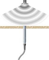
A pressure microphone is for measuring the actual sound pressure as it exists on the surface of the microphone's diaphragm. A typical application is in the measurement of sound pressure in a closed coupler or, as shown below, the measurement of sound pressure at a boundary or wall; in which case the microphone forms part of the wall and measures the sound pressure on the wall itself.
Free-field microphones
A free-field microphone is designed essentially to measure the sound pressure as it existed before the microphone was introduced into the sound field. At higher frequencies the presence of the microphone itself in the sound field will disturb the sound pressure locally. In general, the sound pressure around a microphone cartridge will increase because of reflections and diffraction.
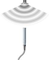
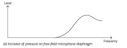
The frequency characteristics of a free-field microphone are designed to compensate for this increase in pressure; hence the output of a free-field microphone is a signal proportional to the sound pressure as it existed before the microphone was introduced into the sound field. A free-field microphone should always be pointed towards the sound source (0° incidence) as shown above. In this situation the presence of the microphone's diaphragm in the sound field will result in a pressure increase in front of the diaphragm depending on the wavelength of the sound and the diameter of the microphone, see curve (a) below.
For a typical ½" microphone, the maximum pressure increase will occur at 26.9kHz, where the wavelength of the sound (λ) coincides with the diameter of the microphone, i.e.:
| λ = | 342 m/s
| ≈ 12.7mm = ½” |
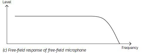
By design, the sensitivity of the microphone must decreases accordingly by an amount which compensates for this increase in acoustical pressure in front of the diaphragm. This is done by increasing the acoustical damping within the cartridge of the microphone so as to obtain the pressure response shown below in curve (b).
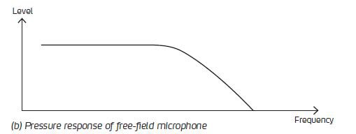
The result is an output from the microphone cartridge which is proportional to the sound pressure as it existed before the microphone was introduced into the sound field, see curve (c) below. Curve (a) above is also called the free-field correction curve for the microphone and must be added to the pressure response of the microphone shown in curve (b), to obtain the characteristics of a free-field microphone shown in curve (c).
Random-incidence microphones
In principle, a free-field microphone requires to be pointed towards the sound source and that the sound waves travel, essentially, in one direction. In some cases, e.g. when measuring in a reverberation chamber or in other highly reflecting surroundings, sound waves will not have a well defined direction of propagation, but will arrive simultaneously at the microphone from various directions.
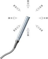
Sound waves arriving at the microphone from the front will cause a pressure increase as described above for a free-field microphone, whereas sound waves arriving from behind the microphone will, to a certain extent, cause a pressure decrease because of the shadowing effects of the microphone. The combined influence of sound waves coming from all directions depends, therefore, on how these sound waves are distributed over these various directions. For measurement microphones, a standard distribution has been defined based on statistical considerations; resulting in a standardized random-incidence microphone.
Pre-polarized or externally-polarized microphones
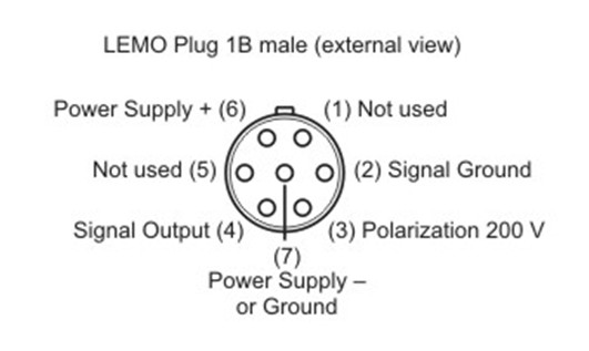
Externally-polarized microphones are used with standard preamplifiers, which have a 7-pin LEMO connector. The preamplifier should be connected to a power module or an analyzer input which can supply the preamplifier with power as well as 200 V polarization.
Pre-polarized microphones are used typically with CCP (Constant Current Power) preamplifiers. These microphones must be connected to an input stage for CCP transducers or be powered by a CCP supply.
National Instruments recommends pre-polarized microphones and constant current powered (CCP) preamplifiers for use with NI devices that provide IEPE (Integrated Electronic Piezo-Electric) signal conditioning.
Frequency range of a microphone
The frequency range of a microphone is defined as the interval between its upper-limiting frequency and its lower limiting frequency.
Upper-limiting frequency
The upper-limiting frequency is linked to the size of the microphone, or more precisely, the size of the microphone compared with the wavelength of sound. Since wavelength is inversely proportional to frequency, it gets progressively shorter at higher frequencies. Hence, the smaller the diameter of the microphone, the higher the frequencies it can measure. On the other hand, the sensitivity of a microphone is also related to its size which also affects its dynamic range.
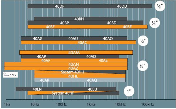
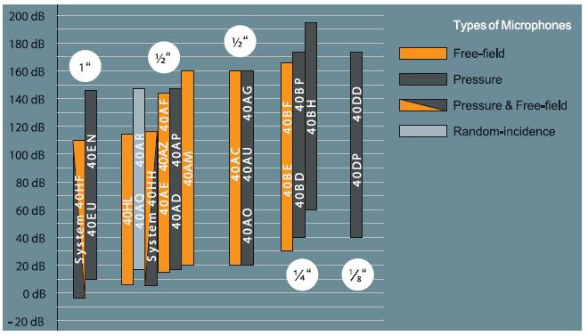
The frequency ranges of various G.R.A.S. microphones are shown in the chart below. The Type or Model number of each microphone is shown. The microphones are grouped according to size of external diameter, i.e. 1”, 1/2”, 1/4” and 1/8”.
Lower limiting frequency
The lower-limiting frequency of a microphone is determined by its static pressure equalization system. Basically, a microphone measures the difference between its internal pressure and the ambient pressure.
If the microphone was completely airtight, changes in barometric pressure and altitude would result in a static deflection of its diaphragm and, consequently, in a change of frequency response and sensitivity.
To avoid this, the microphone is manufactured with a static-pressure equalization channel for equalizing the internal pressure with ambient pressure. On the other hand, equalization must be slow enough to avoid affecting the measurement of dynamic signals.
Dynamic range of a microphone
The dynamic range of a microphone can be defined as the range between the lowest level and the highest level that the microphone can handle. This is not only a function of the microphone alone but also of the preamplifier used with the microphone. The dynamic range of a microphone is, to a large extent, directly linked to its sensitivity.
In general, a microphone with a high sensitivity will be able to measure very low levels, but not very high levels, and a microphone with low sensitivity will be able to measure very high levels, but not very low levels.
The sensitivity of a microphone is determined chiefly by the size of the microphone and the tension of its diaphragm. Generally speaking, a large microphone, with a loose diaphragm, will have a high sensitivity and a small microphone, with a stiff diaphragm, will have a low sensitivity.
Upper limit of dynamic range
The highest levels that can be measured are limited by the amount of movement allowed for the diaphragm before it comes into contact with the microphone’s back plate.
As the level of the sound pressure on a microphone increases, the deflection of the diaphragm will accordingly be greater and greater until, at some point, the diaphragm strikes the back plate inside the body of the microphone. This is ultimately at the highest level the microphone can measure.
In fact, as the deflection of the diaphragm becomes large, the relationship between diaphragm deflection and the consequent change in microphone capacity becomes non-linear and results in distorting the output signal of the microphone. Because of this, the upper limit of the dynamic range is described as that level where distortion reaches 3%. A distortion limit of 10% usually occurs at about 6 dB higher.
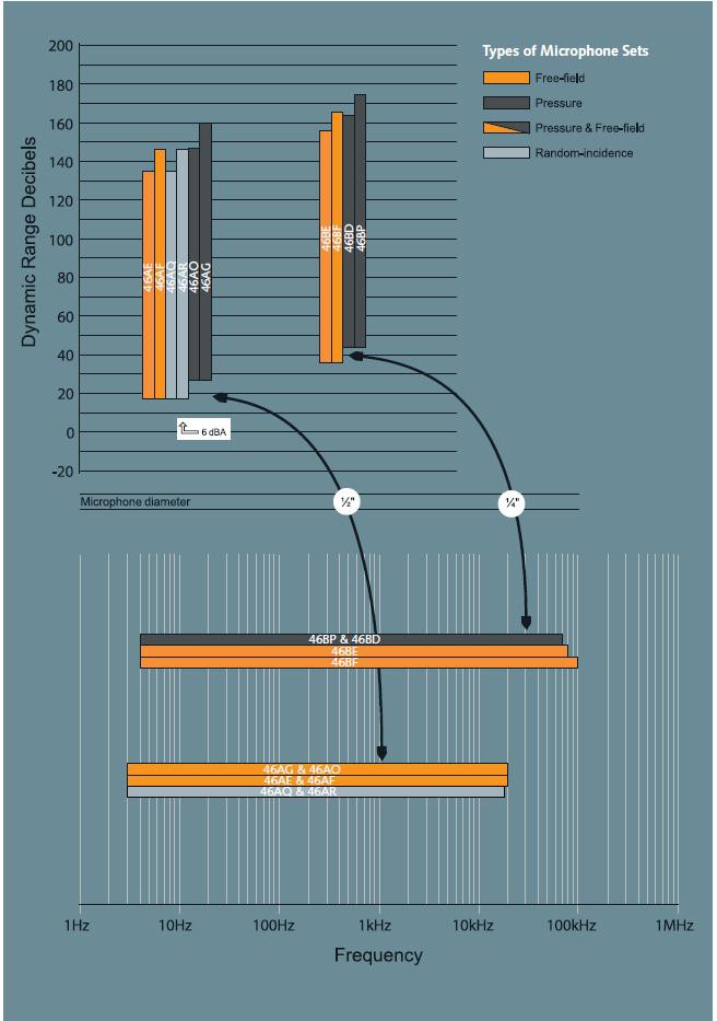
The dynamic ranges of various G.R.A.S. microphones are shown in the chart below.
The Type or Model number of each microphone is shown. The microphones are
grouped according to size of external diameter, i.e. 1”, 1/2”, 1/4” and 1/8”.
Lower limit of dynamic range
The thermal agitation of air molecules is sufficient for a microphone to generate a very small output signal, even in absolutely quiet conditions. This "thermal noise" lies normally at around 5 µV and will be superimposed on any acoustically-excited signal detected by the microphone. Because of this, no acoustically-excited signal below the level of the thermal noise can be measured.
This 5 µV output signal is equivalent to a certain "apparent" sound pressure level which can be calculated from the sensitivity of the microphone. For a microphone with a sensitivity of 50 mV/Pa, this would correspond to an apparent sound pressure of:
|
5 µV | = 0.0001 Pa; in other words around 14 dB re. 20 µPa |
Similarly, for a microphone with a sensitivity of 4 mV/Pa, this would correspond to an apparent sound pressure of:
|
5 µV | = 0.00125 Pa; in other words around 36 dB re. 20 µPa |
Hence, a microphone with a sensitivity of 50 mV/Pa can measure down to about 14 dB whereas a microphone with a sensitivity of 4 mV/Pa can only measure down to about 36 dB.
In practice, a microphone needs to be connected to a high-impedance preamplifier in order to handle the very weak output signal from the microphone. A preamplifier also has a certain amount of noise which will be added to the thermal noise generated by the microphone. See Preamplifiers.
Preamplifiers
The output signal from a microphone is very weak and cannot drive cables, so, it is necessary to mount a preamplifier directly on to the microphone or very close to it. The preamplifier does not normally amplify the microphone signal but converts the high impedance microphone signal to a low impedance signal which can drive long cables etc; for this reason, a preamplifier is sometimes also called an impedance converter.
National Instruments sells microphone sets which combine the microphone and preamplifier into one package. These microphone sets can be found under the Available G.R.A.S. Microphone section at the bottom of the document.
Preamplifier types
Preamplifiers come in two different versions; one is what is normally referred to as "traditional" and the other as CCP. National Instruments recommends pre-polarized microphones and constant current powered (CCP) preamplifiers for use with NI devices that provide IEPE (Integrated Electronic Piezo-Electric) signal conditioning. Both types are available from G.R.A.S. and are described here.
Traditional preamplifiers
Traditional preamplifiers require an external power supply which delivers a supply voltage of either ±15 to ±60 V DC or +28 to +120 V DC. This type of preamplifier is normally connected to a suitable power supply (for example the G.R.A.S. Type 12AK) via a 7-pin LEMO plug, see diagram below, or to an analyzer with a suitable LEMO connector.
CCP preamplifiers
CCP preamplifiers connect to a CCP supply (for example the G.R.A.S. Type 12AL) via a standard coaxial cable and plug (e.g. BNC) or to an analyzer with a CCP input. In a CCP preamplifier, the power supply maintains a constant current superimposed on the same wire carrying the signal, therefore, requiring only a standard coaxial cable and connector.
Preamplifier frequency range
All G.R.A.S. preamplifiers cover a frequency range which tops at 200 kHz, whereas the lower limit of the frequency range is determined by the microphone’s capacitance.
Most G.R.A.S. preamplifiers have an input impedance of 20 GΩ which, combined with the capacitance of the microphone cartridge, forms an RC network that determines the low-frequency cut-off.
A typical microphone, such as the G.R.A.S. Type 40AF, has a capacitance of 17 pF which results in an electrical lower-limiting frequency of 2.7 Hz.
Preamplifier dynamic range
The dynamic range of a preamplifier can be defined as the range between the highest level the preamplifier can handle and the lowest level it can measure. The highest level is related to the voltage supplied to the preamplifier, whereas the lowest level is related to the noise generated by the preamplifier itself.
Upper limit of dynamic range
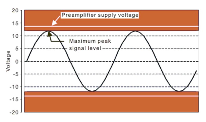
The highest level is related to the voltage supplied to the preamplifier so that the peak-to-peak variation in signal levels that can be handled by the preamplifier is slightly less than the voltage supplied. For example, for a supply voltage of ± 14 V DC, the preamplifier can handle peak signals up to 12 V or peak-to-peak signals up to 24 V, see diagram below.
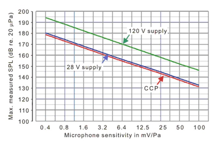
The sound pressure levels which can be measured with a particular preamplifier depends on the sensitivity of the microphone used for the measurements, such that a microphone with a low sensitivity can measure higher levels than a microphone with a high sensitivity, see diagram below.
Lower limit of dynamic range
The lower limit of a preamplifier’s dynamic range is determined by the noise floor of the preamplifier. A typical preamplifier generates a broad-band noise signal of around 3 µV and will mask the microphone's signal if it lies below this.
The noise spectrum of the preamplifier is dominated by low frequencies as shown in the graph below.
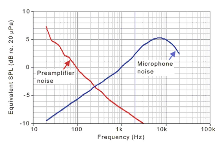
When a microphone is mounted on a preamplifier, the inherent noise of the microphone will be added to the preamplifier noise and the noise floor of the system will be determined by the combined microphone and preamplifier noise.
As the graph above shows, the lower limit of the dynamic range is determined by preamplifier noise at the low frequencies and by microphone noise at the high frequencies.
Microphone Sets
Plug & Play
The microphone sets can be connected directly to all professional measurement systems and as indicated they are available for both CCP and 7-pin LEMO inputs. If your measurement platform supports intelligent transducers according to IEEE 1451.4 (TEDS) you can simply plug in the microphones and they will identify themselves with their specific properties, types and calibration data. A feature especially appreciated by multi-channel users.
Cables
The CCP sets use high-quality coaxial cables, whereas the LEMO sets use a special, soft type of multicore shielded cable. Some sets have a 3 m cable included and others have cables as accessories. If extended cables are to be used you should consider the possible influence on the upper frequency and dynamic ranges. More information about this can be found on gras.dk.
Calibration data
All microphone sets are delivered as a unit and are calibrated accordingly. The sets are delivered with calibration charts including sensitivity values and frequency response curves for the complete set. The sensitivity value can therefore be used directly in your system setup.
Verification and annual calibration
For frequent verification of the measurement chain a sound source will be required. G.R.A.S. supplies a 114 dB sound calibrator for this purpose. Depending on the use and your internal quality control requirements we recommend that the sets are recalibrated at least every second year.
Special Microphones
Special microphones are often required for applications where there are particular requirements surrounding the methods of measurements and configurations as in the following.
Surface microphones for general purpose measurements on planar and curved surfaces. Wide useful frequency range reaching up to 70 kHz and a large dynamic range topping at around 174 dB.
Array microphones for situations where concurrent measurements are required at several points in an array. For example in the analysis of sound fields, sound power and transients. Close manufacturing tolerances together with the advantages of the TEDS chip provide these array microphones with a high degree of interchangeability;
a major advantage when used in multiples forming arrays and matrices.
Outdoor microphones are for permanent outdoor use and encased stainless steel units that can withstand all weathers year after year e.g. in airport noise monitoring systems.
Environmental microphones are smaller units meant for temporary outdoor use in terms of days or weeks, such as in time limited consultant work.
The Low-noise Microphone System can measure pressure levels well below the threshold of human hearing and is amply suitable for use in sound power measurements on even very quiet products. Its very wide dynamic range permits
measurements down to below -2dB re. 20µPa (in 1/3-octave bands) from 20 Hz to 20 kHz. A stand-alone low-noise microphone system, type 40HL, for connecting directly to any analyzer input module with 7-pin LEMO, is now
available.
Intensity Probes from G.R.A.S. comprise two closely spaced, face-to-face microphones and a set of 1/4-inch preamplifiers as well as a control handle. The 1/2-inch and 1/4-inch intensity microphone pairs have been carefully
manufactured and selected to have minimum phase difference.
Probe Microphones for measurements in difficult or inaccessible situations, for
example at high temperatures or conditions of airflow. Its right-angled design makes
it particularly well suited for measurements in exhaust systems and machinery in
general, as well as for scanning surfaces such as loudspeakers and cabinets.
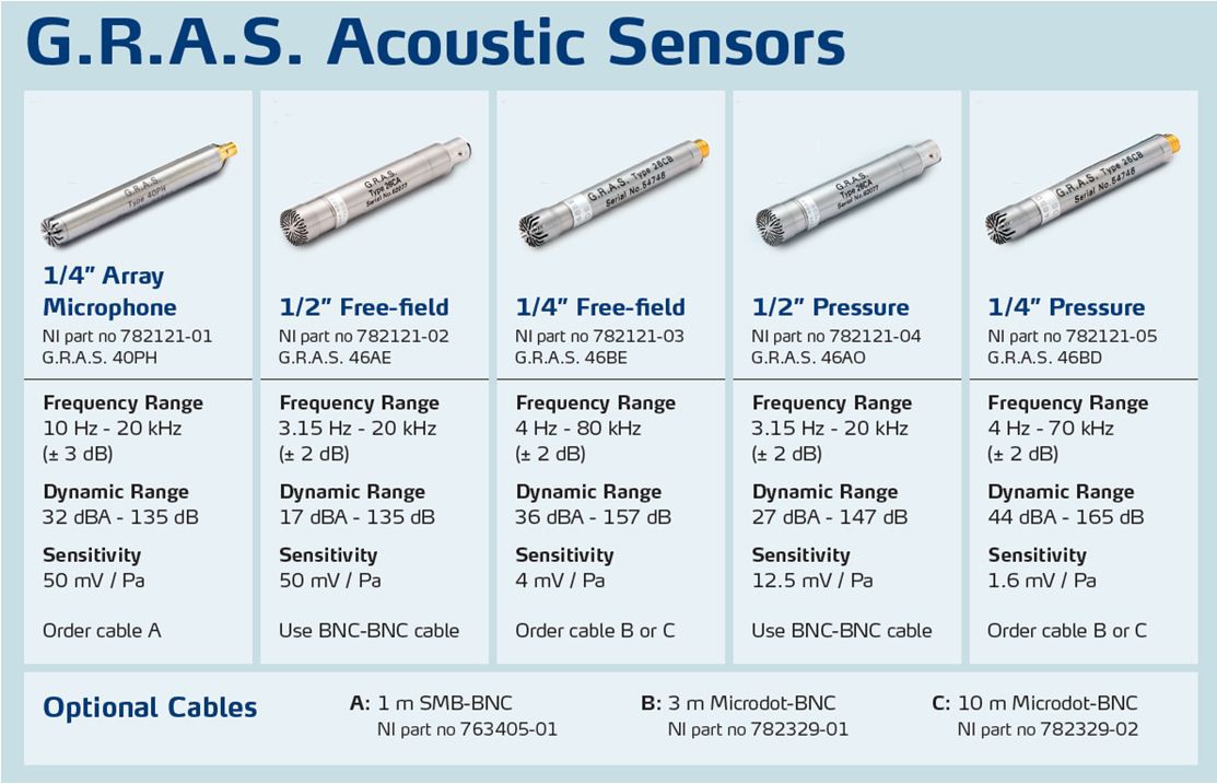
Available G.R.A.S. Microphones at National Instruments
National Instruments offers a variety of G.R.A.S. acoustic sensors for use with NI DSA hardware. These microphones have been tested for compatibility by NI engineers and work with modules that provide IEPE signal conditioning. The microphones contain a Transducer Electronic Data Sheet (TEDS) chip and combine with NI DSA hardware to provide a plug-and-play sensor experience. The microphone types range from array microphones often used in acoustic holography to condenser microphones appropriate for class 1 sound-level measurements.
You can purchase these acoustic sensors from NI using the following links: