Choosing the Right Switch Bandwidth
Overview
When using a PXI switch, it is important to understand how input signals may be affected by the switch bandwidth characteristics and what is required for the application. Determining the bandwidth required by an application is not always straightforward, and using a PXI switch that does not meet the application's signal requirement can lead to poor signal waveform quality.
This article explains what switch bandwidth means, how it affects different signal types, and how to estimate bandwidth requirements so that you can select the appropriate NI PXI switch module for your test system.
Contents
- What Is Switch Bandwidth?
- How Signal Shape Affects Bandwidth Requirements
- Estimating Required Bandwidth
- Summary of How Switch Bandwidth Impacts Module Selection
- Next Steps
What Is Switch Bandwidth?
Switch bandwidth is the frequency range over which a switch can route signals with acceptable insertion loss and distortion. It is commonly specified by the frequency at which insertion loss reaches −3 dB.
Most PXI switches have a bandwidth rating which gives the typical frequency where sinusoidal input signals have a –3dB attenuation due to insertion loss. Frequencies above that bandwidth rating may have greater attenuation.
For example, a switch with a bandwidth rating of 10 MHz implies that the switch has an insertion loss of -3 dB at 10 MHz. If the input signal is a 10 MHz, 1V peak-to-peak sine wave, the output signal will be a 10 MHz, 0.7 V peak-to-peak sine wave.
If the input signal is not purely sinusoidal and has multiple frequency components (like a square wave), applying the ratings can be a little more troublesome. For example, a square wave can have its fundamental frequency below the bandwidth rating while some of the harmonics are above the rating. These harmonics would be attenuated to a higher degree, resulting in different rising and falling edge rates.
How Signal Shape Affects Bandwidth Requirements
Ideal Square Wave
A classic example of a signal with multiple frequency components is an ideal square wave. (refer to Figure 1.) Consider a 2 V peak-to-peak square wave with a fundamental frequency of 1 Hz. The frequency components that make up the square wave are infinite. It is made up of the summation of weighted harmonics.
Equation (1) shows this summation.
For square waves, only odd harmonic terms are used, (e.g. sin t, sin 3t, sin 5t, etc), where the frequency is in radians per second.

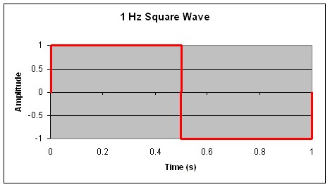
Figure 1. 1 Hz square wave signal over time
Using Equation (1), we can graph the summation of several harmonics. Figure 2 shows this square wave approximated by the summation of different harmonic sine waves: fundamental frequency or 1st harmonics, summation of the 1st, 3rd, and the 5th harmonics and summation from the 1st to the 13th harmonics.
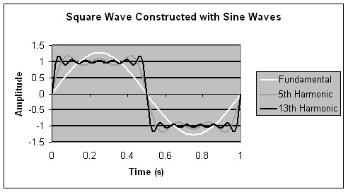
Figure 2. Square wave constructed with sine waves
Once the 5th or 7th harmonic is reached, there is little change in the slope of the edges. For signals like square waves, where the frequency content is known, the switch bandwidth should be based on the highest harmonic passed with minimal attenuation or distortion. If the selection of the switch is based upon the 7th harmonic of the ideal 1 Hz square wave, a switch with a switch bandwidth rating at 7 Hz can be used.
As a rule of thumb, choose a switch for a square wave equal to 7 times the fundamental frequency.
Estimating Required Bandwidth
Rise Time Bandwidth Approximation
For other signals where the frequency components are not known, the bandwidth may be approximated using rise time. The rise time is related to the switch bandwidth rating by the approximation:

Where tr is the time the signal takes to go from 10% to 90% of its amplitude. See Figure 3.
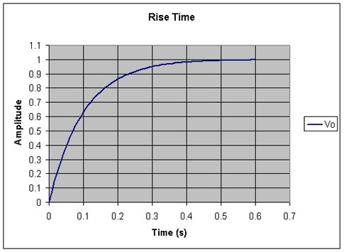
Figure 3. Exponential rise time response
For the signal shown in Figure 3, the rise time is about 0.22 seconds.
To illustrate this approximation, consider the signal shown in Figure 4.

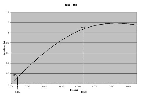
Figure 4. Rise time (10% to 90%)
The rise time from 10% to 90% of the amplitude of this signal is 0.039 s. The switch bandwidth rating can then be approximated as 8.97 Hz. Figure 3 is a graph of the summation of the 1st, 3rd, 5th, and 7th harmonics of the 1 Hz ideal square wave shown in Figure 1.
System Response
A signal passing through a switch is modified. The extent of this modification or filtering depends on the combined response of the signal and the switch. Using the rise time from 10% to 90% of the signal amplitude, the system response can be stated in the following equation:

Where Tsys, Tsig and Tsw are the rise times of the system, signal, and switch respectively.
To minimize the effect of the switch on the signal, the switch bandwidth should be much higher (i.e. have a shorter rise time) than the signal bandwidth.
Switch Selection Example
Consider a signal rise time of Tsig = 9 ns.
Find a switch bandwidth where only a 2 % increase of the signal rise time occurs.
A 2% increase in rise time results in a system rise time of:
Using Equation (3), the switch rise time be calculated
Using Equation (2), the switch bandwidth rating can be approximated:
Selecting a switch with a -3 dB bandwidth of 193 MHz will allow only a 2% increase in the signal rise time.


Signal, Switch, and System Bandwidth Relationship
In a more general way, the system bandwidth can be expressed using the allowed reduction in input signal bandwidth (p):
Using Equation (2) and (3) we can relate the bandwidth:
Substituting Bsys from Equation (4) into Equation (5), the switch bandwidth becomes:
Figure 5 is the graphical representation of this relationship.

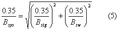
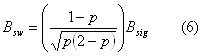
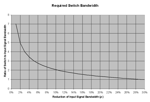
Figure 5. Required switch bandwidth
For this example, only the attenuation due to switch bandwidth has been considered. Effects due to impedance mismatch are not covered here.
From our example the input signal has a -3 dB bandwidth of:
From the graph on Figure 5, to allow for a 2% reduction of input signal bandwidth, we need to select a switch with a bandwidth 5 times the bandwidth of the input signal: 194 MHz.

Summary of How Switch Bandwidth Impacts Module Selection
Switch bandwidth is an important consideration when selecting a switching solution. Knowing the highest frequency that must pass through a switch with minimal attenuation is significant for preserving signal integrity.
- For sine wave input signals, the switch bandwidth rating is the highest recommended sine wave frequency and may have -3 dB of attenuation. If attenuation less than -3 dB is required, select a switch with a higher bandwidth rating.
- For square wave input signals, the higher-frequency harmonics must be considered to maintain a good signal edge. For a given fundamental frequency, select a switch with a bandwidth frequency seven times greater than the fundamental frequency.
- For other input signals, use the rise time bandwidth approximation explained in this document.
Next Steps
The broad portfolio of NI switch modules offers bandwidths and relay technologies optimized for a wide range of test applications. Explore the following resources to browse the NI switch portfolio, learn how to select the right relay technology, and discover the advantages of NI switching solutions.