Troubleshooting DC Operating Point Analysis Failures
Overview
Multisim features a comprehensive suite of SPICE analyses for examining circuit behavior. These analyses range from the basic to sophisticated. Each analysis helps you to obtain valuable information such as the effects of component tolerances and sensitivities. For each analysis you need to set settings that will inform Multisim exactly what to analyze, and how.
Multisim simplifies the procedure for an advanced analysis by providing a configuration window. This abstracts away the complexities associated with SPICE syntax and configuration of an analysis. With this window you merely need to specify the parameter values and output nodes of interest.
This tutorial is part of the National Instruments SPICE Analysis Fundamentals Series. Each tutorial in this series provides you with step-by-step instructions on how to configure and run the different SPICE analyses available in Multisim.powerful simulation and analysis while abstracting the complexity of SPICE syntax.
Contents
Introduction
DC Operating Point Analysis may fail to converge for various reasons. The initial estimates for the node voltages may be too far off, the circuit may be unstable or bi-stable (there may be more than one solution to the equations), there may be discontinuities in the models or the circuit may contain unrealistic impedances.
Troubleshooting Techniques
Use the following techniques to solve many convergence problems and analysis failures. Before you proceed, identify which analysis is causing the problem (keep in mind that DC Operating Point Analysis is often performed as the first step of other analyses). In each of the following solutions, begin with step 1, then continue performing the subsequent steps, in order, until the problem is solved.
- Check the circuit topology and connectivity. Make sure that:
- The circuit is grounded.
- The circuit is correctly wired, and includes no dangling nets or stray parts.
- You have not confused zeroes with the letter O.
- The circuit has a ground node and every node in the circuit has a DC path to ground. Make sure no sections of your circuit are completely isolated from ground by transformers, capacitors, etc.
- Capacitors and voltage sources are not in parallel.
- Inductors and current sources are not in series.
- All devices and sources are set to their proper values.
- All dependent source gains are correct.
- Your models/subcircuits have been correctly entered.
- Show all net names. Check the net name assigned to ground components. All grounds must be indicated by net name 0 (zero). If otherwise, delete a ground and replace by another one from the parts bin.
- Check for duplicate net names in the circuit. Each net must have a unique name. Reassign if necessary by double-clicking the wire indicating a duplicate net name and typing in another unique name.
- If working with digital circuits make sure that both, earth and digital grounds are left on the workspace.
- Copy and then paste your circuit into a new file. Simulate the circuit again.
If the problem persists, adjust the following parameters:
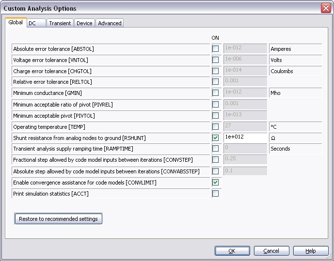
- Select Simulate»Analyses»DC Operating Point, select the Analysis Options tab, enable Use Custom Settings and click on Customize. The Custom Analysis Options window appears as shown in the following figure:
Figure 1. Custom Analysis Options window.
- Select the Global tab and make the following changes:
- Reduce the Shunt resistance from analog nodes to ground [RSHUNT] value by a factor of 100.
- Increase the Minimum Conductance [GMIN] by a factor of 10. Note: GMIN = 1/Rp, where Rp is the smallest parasitic resistance value in the circuit.
- Select the DC tab and make the following changes:
- Set the DC iteration limit [ITL1] value to 500 or more. By increasing ITL1, the extra iterations will only be used if they are needed. ITL1 set to 1000 covers about 90% of circuits.
- Set the Number of source steps [ITL6] value to 500.
In the schematic, you can also use the .Nodeset command to set a DC voltage level if possible.
- Double-click the wire connected to a net in question, check Use NODESET for DC and type in a DC voltage.
When running DC Operating Point Analysis for a circuit that contains ammeters and voltmeters (indicators) and their internal settings (resistance) have been changed from their default values, the simulation results indicated by DC Operating Point Analysis will be incorrect. Remove ammeters/voltmeters to correct the problem. The results are correct if no changes were applied to ammeter/voltmeter internal settings.