NI VeriStand Add-on - NI Fault Insertion Units
Overview
Add deterministic hardware fault insertion to NI VeriStand by using the example Custom Device to control the NI PXI-2510, 2512, and 2514 Fault Insertion Units (FIU).
Contents
- Installation:
- The NI PXI-2510 Fault Insertion Unit:
- The NI PXI-2512 Fault Insertion Unit:
- The NI PXI-2514 Fault Insertion Unit:
- Fault Insertion Application
- How To Use the NI PXI-2510 FIU in NI VeriStand:
- Support and Contact
Installation:
Before using the NI VeriStand Custom Device for the NI PXI-2510, 2512, or 2514:
- Copy the contents of the provided GitHub folder into:
<Public Documents>\National Instruments\VeriStand 20xx\Custom Devices - Restart NI VeriStand.
Please note Pre-2019 releases would use the FIU Custom Device and post 2019 releases would use the default Routing and Faulting custom device.
For more information on Custom Devices, please see the white paper on this topic.
The NI PXI-2510 Fault Insertion Unit:
The NI PXI-2510 fault insertion unit (FIU) is designed for use in hardware-in-the-loop (HIL) applications and electronic reliability tests. Each module has a set of feedthrough channels, which when closed make the switch transparent to the system. You can open or short these channels to one of two fault buses, each of which offers a multiplexer with four possible inputs. You can use this architecture to simulate open or interrupted connections as well as shorts between pins, shorts to battery voltages, and shorts to ground on a per-channel basis. When controlled with the NI LabVIEW Real-Time Module, this FIU is ideal for validating the reliability of control systems such as engine control units (ECUs), full authority digital engine controls (FADECs), and more with up to 2 A loading conditions.
The NI PXI-2512 Fault Insertion Unit:
The NI PXI-2512 fault insertion unit (FIU) is designed for use in hardware-in-the-loop (HIL) applications and electronic reliability tests. Each module has a set of feedthrough channels, which, when closed, make the switch transparent to the system. You can open or short these channels to one of two fault buses. You can use this architecture to simulate open or interrupted connections as well as shorts between pins, shorts to battery voltages, and shorts to ground on a per-channel basis. When controlled with the NI LabVIEW Real-Time Module, this FIU is ideal for validating the reliability of control systems such as engine control units (ECUs), full authority digital engine controls (FADECs), and more with up to 10 A loading conditions.
The NI PXI-2514 Fault Insertion Unit:
The NI PXI-2514 fault insertion unit (FIU) is designed for use in hardware-in-the-loop (HIL) applications and electronic reliability tests. Each module has a set of feedthrough channels, which, when closed, make the switch transparent to the system. You can open or short these channels to one of two fault buses. You can use this architecture to simulate open or interrupted connections as well as shorts between pins, shorts to battery voltages, and shorts to ground on a per-channel basis. When controlled with the NI LabVIEW Real-Time Module, this FIU is ideal for validating the reliability of control systems such as engine control units (ECUs), full authority digital engine controls (FADECs), and more with up to 40 A loading conditions.
Fault Insertion Application
A typical FIU placement in a dynamic test system for an Engine Control Unit (ECU) is shown below.
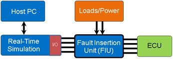
The FIU is designed to insert fault conditions between the real-time hardware-in-the-loop (HIL) simulation systems and the ECU/Device Under Test (DUT).
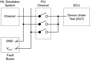
To insert fault conditions, internal relays are configured to create short-circuit connections and open circuits. As mentioned above, automated test applications commonly use the following fault conditions:
- Open Circuits
- Short to Ground or Power
- Pin-to-Pin Short
FIUs with switchable fault bus inputs can be used to create additional fault conditions, such as a Pin-to-Pin Short Through a Load.
No-Fault Operation
In an FIU’s no-fault setting, test equipment is directly connected to DUT signal lines through the FIU module.
Open Circuit Faults
In an open circuit or interrupt fault, the signal line between the test application and DUT is left open to determine how the DUT behaves after a signal interruption.
Short to Ground or Short to Power
To simulate shorts to ground or power, the signal line is connected from an external fault line or fault bus to the DUT. The fault buses can be configured to simulate power supply lines or system ground.
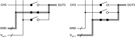
Pin-to-Pin Short
In a pin-to-pin short, the DUT signal line is connected to one or more additional DUT signal lines.
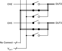
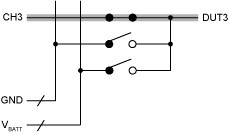
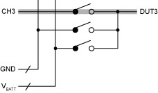
Example Pin-to-Pin Short Through a Load Using the NI PXI-2510
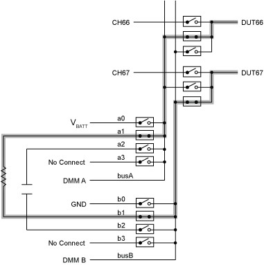
The NI PXI-2510 has two fault buses. Each fault bus has four switchable inputs to select among multiple fault conditions such as battery voltage (Vbatt), ground (GND), and other fault voltage potentials. The non-switchable input to each fault bus is intended for monitoring the fault bus with a DMM. The switchable fault bus inputs allow for another fault condition: a pin-to-pin short through a load.
The following example shows a pin-to-pin short through a load using the NI PXI-2510:
How To Use the NI PXI-2510 FIU in NI VeriStand:
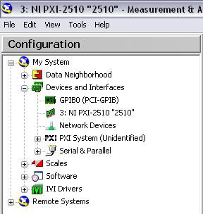
- Configure the NI PXI-2510 in Measurement and Automation Explorer. In the picture below, the NI PXI-2510 was given the DAQmx Device Name "2510".
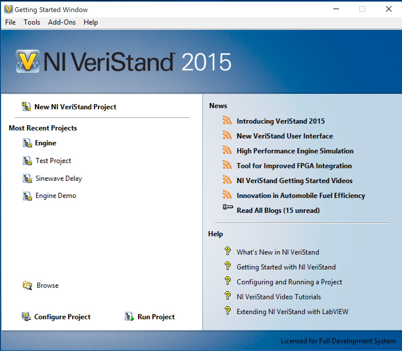
- Launch NI VeriStand. The Getting Started page will appear.
- Select a Project in which to add the Custom Device for the NI PXI-2510. To create a new Project, select New NI Veristand Project on the NI VeriStand Getting Started Window.
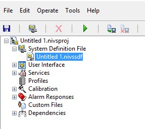
- Once he desired Project has been selected, click System Definition File to expand the tab and double click in the file: -Name of your project-.nivssdf
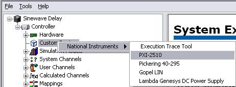
- Add a Custom Device for the NI PXI-2510 FIU. Right-click Custom Devices in the configuration tree and select National Instruments » PXI-2510.
- Insert the DAQmx Device Name "2510" and click OK. The Custom Device for the NI PXI-2510 FIU will be created.
- The Custom Device for the NI PXI-2510 FIU has a Channels Section and a Fault Bus Section. The Channels Section has 68 Items, one for each of the 68 FIU channels on the NI PXI-2510. The Fault Bus Section has 2 Items, one for each of the fault buses on the NI PXI-2510. The default Item settings can be changed as follows:
Channels: The "Name (Alias)" for each channel and the Fault Default Value can be changed. The Fault Default Value sets the default state for the channel. The different options include: Default, DUT Pass Through, DUT Open, DUT Pass Through and FB A, DUT Pass Through and FB B, DUT FB A, and DUT FB B.
Default: Does not make a call to the driver.
DUT Pass Through: Close relay between channel and DUT, Open relays between buses and DUT.
DUT Open: Open relay between channel and DUT, Open relays between buses and DUT.
DUT Pass Through and FB A: Close relay between channel and DUT, Close relay between busA and DUT, Open relay between busB and DUT.
DUT Pass Through and FB B: Close relay between channel and DUT, Open relay between busA and DUT, Close relay between busB and DUT.
DUT FB A: Open relay between channel and DUT, Close relay between busA and DUT, Open relay between busB and DUT.
DUT FB B: Open relay between channel and DUT, Open relay between busA and DUT, Close relay between busB and DUT.
Fault Buses: Fault Bus A and Fault Bus B have 6 different options: Default, Input 0, Input 1, Input 2, Input 3, and Main Bus Only.
Default: Does not make a call to the driver.
Input 0: Close relay between Input 0 and Fault Bus, Open relays between Inputs 1, 2, and 3 and Fault Bus. Note that the Main Bus is still connected to the Fault Bus.
Input 1: Close relay between Input 1 and Fault Bus, Open relays between Inputs 0, 2, and 3 and Fault Bus. Note that the Main Bus is still connected to the Fault Bus.
Input 2: Close relay between Input 2 and Fault Bus, Open relays between Inputs 0, 1, and 3 and Fault Bus. Note that the Main Bus is still connected to the Fault Bus.
Input 3: Close relay between Input 3 and Fault Bus, Open relays between Inputs 0, 1, and 2 and Fault Bus. Note that the Main Bus is still connected to the Fault Bus.
Main Bus Only: Opens relays between Inputs 0, 1, 2, and 3 and the Fault Bus. The Main Bus line is the only one connected to the Fault Bus.
- Save the current configuration and close the System Explorer window. Now that the Custom Device for the NI PXI-2510 has been added in the System Explorer, controls can be inserted into the Workspace file. Under Active Project, verify the Workspace file and Target IP address, and then click Run Workspace.
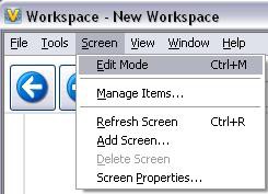
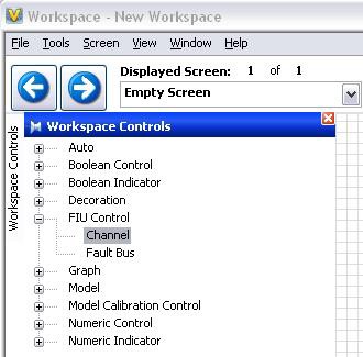
- To add controls, select Screen » Edit Mode (CTRL+M) from the menu.
Click Workspace Controls to view the available Workspace Controls that can be added to the Screen. Expand FIU Control to view the Channel and Fault Bus controls.
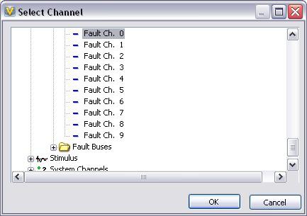
- Select Channel and drag the control onto the Screen. An Item Properties dialog will appear allowing you to configure the properties of the control. On the General tab, click the folder icon to browse for the NI PXI-2510 Custom Device. Expand the folders until the individual Fault Channels are shown. Select Fault Ch. 0 and click OK.
Note: After clicking the folder icon, if the Custom Device for the NI PXI-2510 was not shown, then it is likely the Custom Device was created under another Workspace.
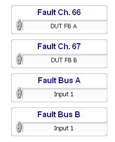
- Drag additional Channels and Fault Buses onto the Screen until the Screen shows each of them that are to be controlled in the application. Select Screen » Edit Mode from the menu. The NI PXI-2510 is now being controlled! Change the control values as necessary to operate relays and create the hardware configurations required in the application.
`

Support and Contact
We do not regularly monitor Reader Comments posted to this page. If you encounter a problem with this add-on, or if you have suggestions for a future revision, please post to the forum for this add-on Fault Insertion Units Add-On Feedback Forum. You must use this feedback forum for support. Do not call NI for support for this add-on.
This add-on is provided as open-source software. If it does not meet your exact specification, you are encouraged to modify the source code to meet your needs. It is not officially supported by NI.
National Instruments does not support this code or guarantee its quality in any way. THIS EXAMPLE PROGRAM IS PROVIDED "AS IS" WITHOUT WARRANTY OF ANY KIND AND SUBJECT TO CERTAIN RESTRICTIONS AS MORE SPECIFICALLY SET FORTH IN NI.COM'S TERMS OF USE (http://ni.com/legal/termsofuse/unitedstates/us/).