From Friday, April 19th (11:00 PM CDT) through Saturday, April 20th (2:00 PM CDT), 2024, ni.com will undergo system upgrades that may result in temporary service interruption.
We appreciate your patience as we improve our online experience.
From Friday, April 19th (11:00 PM CDT) through Saturday, April 20th (2:00 PM CDT), 2024, ni.com will undergo system upgrades that may result in temporary service interruption.
We appreciate your patience as we improve our online experience.
The specification manuals for NI CompactDAQ and CompactRIO chassis and controllers provide the technical details necessary to determine or choose which chassis or controller are best suited for your application, and as a reference to validate performance during system development. This document provides definitions of the terminology used, in a glossary format, to illustrate the importance and relevance of each specification.
This guide is broken up into the same sections as most NI specifications manuals. Terms and definitions below are listed in alphabetical order and may occur in a different order in the specification manuals. This guide exclusively applies to CompactDAQ and CompactRIO Chassis and Controllers. Other NI product families such as, Multifunction DAQ 60xx, 61xx, 62xx, and 63xx families (formerly B, E, S, M, and X Series), Multifunction RIO 78xx R Series, Digital Multimeters, Scopes/Digitizers and other instruments may use different terminology or methods to derive specifications and as such, this guide should not be used as a reference for devices other than those in the CompactDAQ and CompactRIO families. While C Series modules are used with CompactDAQ and CompactRIO chassis and controllers, their specifications are not included in this guide.
This guide will use the DAQ-9178 and cRIO-9068 chassis as references throughout. To follow along with these specifications, follow these links: cDAQ-9178 and cRIO-9068.
First, it is important to note the categorical difference between various specifications. NI defines the capabilities and performance of its Test & Measurement instruments as either Specifications, Typical Specifications, and Characteristic or Supplemental Specifications. See your devices' specifications manual for more details on which specifications are warranted or typical.
Some specifications for a C Series system are designated by the modules, while others are designated by the backplane. Some specifications are also dependent on system configuration.
In general, a cDAQ chassis or controller provides timing, triggers, counters, and data transfers between modules and a host computer or the onboard controller. A CompactRIO controller features a real-time processor and reconfigurable FPGA for high-speed control and custom timing and triggering.
Both types of backplanes interface directly with C Series modules, which use the timing and control provided by the backplane for their inputs, outputs, or other functions. The modules perform their own acquisition and generation, and communicate that data back to the chassis which then transfers that data to the user. Some modules also contain their own signal conditioning.
All C Series modules have their own safety certifications, power requirements, and other specifications. Reference your module's datasheet or specifications documents for specifications not found in this document.
(CompactDAQ) cDAQ chassis can store data in an onboard FIFO when performing input or output tasks.
Chassis have a dedicated FIFO for input and output tasks. However, the FIFO is shared across all channels within that task. For analog input, NI-DAQmx implements data transfer mechanisms to ensure that the data stored in the FIFO is transferred to the PC buffer fast enough so that the onboard FIFO is not overrun. For analog output, NI-DAQmx implements data transfer mechanisms to ensure that data in the PC buffer is transferred to the onboard FIFO fast enough such that the FIFO is not underrun. For analog output, there are user-selectable properties to specify whether or not to use the PC buffer at all, and to regenerate a single waveform from just the onboard FIFO.
The cDAQ-9178 has an input FIFO that can store 127 samples per slot. This means that an input task with four channels acquiring data at a rate of 512 S/s/ch would overrun the onboard FIFO in less than 63 milliseconds (512 S/s/ch * 4 ch * 0.0625 s = 128 samples). NI-DAQmx uses DMA to transfer data from the FIFO to the PC Buffer to avoid the overrun.
Waveform Acquisition (DI) FIFO
(CompactDAQ/CompactRIO) The rate that samples are generated can be controlled by hardware or software. With hardware timing, a digital signal, such as a clock onboard your chassis, controls the rate of generation. A hardware clock can run much faster than a software loop. A hardware clock is also more accurate and deterministic than a software loop. Hardware-timed tasks use onboard buffers to load multiple samples, which can be either regenerated or non-regenerated.
With software timing (or non-hardware-timed task), the acquisition or generation occurs only as fast as the software can iterate. This speed is limited by the performance of the code, hardware system and computer operating system. To improve speed and consistency with a software loop, you can use a real-time operating system (RT OS). To get the most precise and granular control, you can program an FPGA, like what is found on a cRIO.
Timing, Hardware Versus Software - NI-DAQ™mx Help
(CompactDAQ) Onboard regeneration allows the chassis to reproduce data from onboard memory. It is also referred to as onboard looping. Using onboard regeneration can affect the number of channels supported, maximum update rate, and ouput FIFO size.
Using onboard regeneration with the cDAQ-9178 allows for support of 16 analog output channels, updating at a maximum of 1.6 MS/s, and have an output FIFO size of 8,191 samples between all channels. If you load a single period of a waveform, you can use onboard regeneration to produce a continuous signal.
(CompactDAQ) Non-regeneration relies on new samples to be constantly loaded from the user's application to avoid an underflow error. This method results in constant communication over the bus, therefore update rates are more limited on buses with lower throughput. Network latency can also affect the maximum achievable update rates over Ethernet or wireless connections.
When using non-regeneration on the cDAQ-9178, the number of analog output channels supported and the maximum update rate are determined by the modules, whereas the output FIFO size is 127 samples per slot. Non-regeneration can be used whenever outputting aperiodic signals, or when traffic on the bus is not a concern.
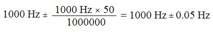
(CompactDAQ/CompactRIO) When generating a clock signal on a chassis for timing signals, the actual frequency generated will be within the timing accuracy. This specification is derived from the accuracy of the onboard crystal oscillator. Timing accuracy is typically measured in parts per million (ppm). To convert this accuracy value to hertz, multiply the sample rate by the accuracy value and divide by 1 million. The frequency of the clock is not likely to change drastically from cycle to cycle.
The cDAQ-9178 has a timing accuracy of 50 ppm for both analog input and output. For an analog output task with an update rate of 1,000 S/s, the sample clock will run at 1,000 Hz ± 50 ppm. In Hz, this comes out to:
(CompactDAQ) Sample and update rates for analog input and output tasks are restricted to discrete values when using an onboard timing engine. The difference in clock periods between two adjacent rates is known as timing resolution. NI-DAQmx will coerce a selected frequency up to the next available frequency if it cannot generate the exact one specified by the user.
The cDAQ-9178 has a specified timing resolution of 12.5 ns for analog input and output. This means that it can acquire or generate data at integer multiples of 12.5 ns. For example, 32,000.000 Hz and 32,012.805... Hz are two adjacent frequencies, because their clock periods are 31.2500 µs and 31.2375 µs, respectively. To find the next available frequency, add or subtract the timing resolution to a known clock period.
(CompactDAQ) Update rate specifies how often the DAC converts data from digital to analog values. When using onboard regeneration, the maximum update rate is determined by the cDAQ chassis. When using non-regeneration, the maximum update rate is often determined by the C Series Module being used. Most C Series Modules have a single DAC per analog output channel, but will all share the FIFO where the analog output data is stored. The rate at which data can be read from this FIFO and transferred to the different DACs onboard can limit the update rate when using multiple AO channels on the same module. Update rate is measured in samples per second (S/s) when outputting from a single channel, or samples per second per channel (S/s/ch) when outputting from multiple channels.
The cDAQ-9178 has a maximum update rate of 1.6 MS/s when using onboard regeneration. This is the maximum rate for all channels combined.
(CompactDAQ) Triggers are signals that cause the C Series Module to perform some action such as starting, stopping, or pausing an acquisition or generation. In cDAQ systems, triggers can come from any module PFI terminal, from onboard clock sources, or from chassis PFI connections. These triggers can serve a variety of functions for analog inputs, analog outputs, and counters.
The cDAQ-9178 can source triggers from any module PFI terminal, or from BNC connections on the chassis. These triggers can be used for a variety of data acquisition functions.
(CompactDAQ) Indicates whether the digital signal is active high or active low.
The cDAQ-9178 offers software-selectable polarity for most signals.
(CompactDAQ) Programmable Function Interface (PFI) lines allow the routing of timing, trigger and other digital signals across the backplane of cDAQ chassis. The module PFI characteristics describe the signals that can be routed from the C Series modules to the PFI lines found on the chassis backplane, including their timing frequency range. Exceeding the maximum frequency may result in unexpected behaviors.
The cDAQ-9178 can support input and output PFI signals from 0 to 20 MHz on its module PFI lines.
(CompactDAQ) Programmable Function Interface (PFI) lines allow the routing of timing, trigger, and other digital signals across the backplane of some cDAQ chassis. The chassis PFI characteristics describe the signals that are externally accessible to the cDAQ chassis without the need for a module. Typically these lines have additional constraints for maximum frequency, cable length, and cable impedance when compared to Module PFI lines.
The cDAQ-9178 can support up to a 1 MHz input or output signal on its BNC connector. The PFI connections have different DC Characteristics for input and output.
(CompactDAQ) Digital I/O module capabilities are determined by the type of digital signals that the module is capable of measuring or generating.
For more information, refer to your chassis user manual at ni.com/manuals.
The cDAQ-9179 supports both serial and parallel modules. The difference affects certain specifications, such as waveform acquisition (DI) FIFO size, and waveform generation (DO) FIFO size.
(CompactDAQ) Determines the rate that you can acquire digital waveform data. This specification is usually dependent on the host PC when streaming to application memory, but is set by the device in other modes.
The cDAQ-9178 has a sample clock frequency of 0 to 10 MHz in finite mode, and the specific value can be set in software. When streaming to application memory, the frequency depends on the host PC.
(CompactDAQ) When reading digital waveform data, there is a temporary storage element onboard the chassis that buffers the data, known as the FIFO. NI-DAQmx copies data from this FIFO into a block of memory in RAM, known as the PC Buffer. From there, an ADE, such as LabVIEW, copies the data into application memory. The size of this FIFO and the rate that the data is being stored determine how often the NI-DAQmx driver copies the data to avoid an overflow condition.
The cDAQ-9178 has a digital waveform acquisition FIFO of 127 samples per slot. This means that if you are acquiring data at a rate of 50 kS/s from any given slot, the onboard FIFO would overflow in about 2.5 ms if the NI-DAQmx driver did not transfer the data in the PC buffer.
(CompactDAQ) There is temporary storage onboard cDAQ chassis that buffer data points in a FIFO data structure. The FIFO size sometimes decreases when higher numbered slots are used in devices with eight or more slots. If only a single digital waveform is needed, the pattern can be loaded onto the FIFO to avoid transferring data over the bus many times.
The cDAQ-9178 has a digital waveform generation FIFO of 2,047 samples. For example, if you are using the digital output for I2C communication at a data rate of 100 kS/s, the entire FIFO will be output in 20 ms. This means that the user should call NI-DAQmx Write more frequently than that to continue to stream data to the FIFO. If doing data rate testing, then a single pattern can be loaded into the FIFO using the NI-DAQmx API and output at different data rates without ever having to write new data across the bus.
(CompactDAQ) Counter measurements, position measurements, and output applications all refer to different tasks that the counters can perform. For more information on implementing these applications and measurements, refer to your cDAQ device's user manual at ni.com/manuals.
(CompactDAQ) The first-in-first-out (FIFO) memory element onboard cDAQ chassis is used to buffer samples of data for either input or output applications. For counter input applications, data points, such as the counter value at specific intervals, are stored in the FIFO before DAQmx automatically transfers the data to pre-allocated block of PC RAM. The FIFO is used for counter output applications to store a sequence of duty cycle and frequency values to alter the shape of the waveform being generated. A larger FIFO is useful as it reduces the amount of traffic on the data bus since larger blocks of data can be transferred less frequently than devices with a smaller FIFO.
The cDAQ-9178 has a 127-sample FIFO for each counter, allowing for 127 different parameters to be configured for a pulse train generation before additional transfers across the bus are needed. If the counter is being used for pulse measurement, the FIFO will store the count of clock ticks between edges of a measured signal.
(CompactDAQ) Counter timing signals, or inputs, are digital signals that control functions of the counter. Most counters have eight inputs:
For more information about these signals and how they can be routed, refer to the your cDAQ device's user manual at ni.com/manuals.
The cDAQ-9178 has 4 counters built into the chassis, with 8 inputs each that can each be configured independently. If one counter is used for measuring quadrature encoders, then inputs A and B would be connected to the encoder. If another counter is used for single pulse-width measurement, then the source, gate, and HW_Arm inputs would be connected. You can expand beyond the four counters in the backplane to reach up to 64 counters, with supported counter I/O modules.
(CompactDAQ) The range of frequencies that the onboard counters can output when configured for pulse train generation. The output frequency depends on the base clock being used, and an external base clock may lower the maximum frequency.
The cDAQ-9178 general purpose counters can produce frequencies from 0 to 20 MHz. The exact frequency can be configured in DAQmx.
(CompactDAQ) The number of bits that a counter can use to represent a number. When a general-purpose counter is configured to output a pulse, the length of time that the pulse is active is represented by the value in the counter's register. The combination of this value and the rate that the counter is counting (set by the counter's base clock) determine the maximum pulse width that can be accomplished. Similarly when using a counter to measure the pulse width of a signal, the maximum pulse width that can be registered is determined by the counter base clock and the resolution of the counter. If a signal exceeds the maximum pulse width the counter will roll over and the DAQmx API will return an error. For this reason, it is important to know how to calculate maximum signal parameters.
Counters with higher resolution provide more flexibility when making the tradeoff between resolution and length of measurements/generations. Refer to the following graph for more details on this tradeoff.
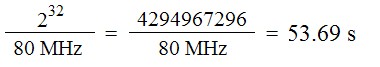
The cDAQ-9178 backplane uses 32-bit counters for counter input and counter output tasks. If a counter input task is configured to measure pulse width, we can calculate the maximum pulse width that can be measured by calculating the maximum counter value and dividing by the counter's internal base clock rate. The 80 MHz counter base clock will allow for 12.5 ns precision, so that base clock will be selected for this example.
(CompactDAQ) The internal base clock for a counter is the signal that will cause the counter's value to increment/decrement depending on the state of the gate terminal. The period of this clock determines the resolution in seconds for a signal being measured or generated but also determines how quickly the counter will roll over when measuring or generating long pulses. For any counter measurement or application, there is a ±1 timebase period quantization error, so to minimize the amount of quantization error, it is important to select the fastest possible base clock for your application.
When performing a measurement using the cDAQ-9178 the three internal base clocks that can be used have rates of 100 kHz, 20 MHz, and 80 MHz. These base clocks provide a resolution ranging from 10 µs to 12.5 ns. If a pulse width modulated (PWM) signal of 125 kHz and 35% duty cycle is applied, the actual pulse width in seconds is 2.8 µs. This is below the resolution of the 100 kHz base clock so it cannot be used for this measurement. The 20 MHz clock has a resolution of 50 ns, so it can perfectly measure the duration of this signal ± 1 base clock pulse. This results in a measurement of 2.8 µs ± 0.05 µs, or an error of about 1.8 %. This same measurement on the 80 MHz clock will result in a measurement of 2.8 µs ± 0.0125 µs for an error of 0.45 %. In this case, the 80 MHz clock can measure a pulse width up to about 34 seconds before the counter rolls over, so this pulse width of 2.8 µs is well below the maximum limit.
(CompactDAQ) If a specific base clock rate is needed, most cDAQ devices allow for the use of an external base clock. This clock serves all the same purposes as an internal base clock, but is externally provided by the user. The maximum rate of an external base clock is dependent on the chassis.
The cDAQ-9178 has an external baseclock frequency range from 0 to 20 MHz. If the internal base clock rates of 80 MHz, 20 MHz, or 100 kHz are not suitable for your application, you may use an external clock in that frequency range.
(CompactDAQ) The accuracy of an internal base clock directly impacts the accuracy of any measurement or frequency generation from a general-purpose counter. This accuracy is also inherited from the overall device timebase accuracy, meaning that the accuracy of this clock can be improved if a higher accuracy master timebase is externally provided.
The cDAQ-9178 has a base clock accuracy of 50 ppm. If a user wanted to generate a 12.8 MHz free running clock with this device, the following calculation can be used to determine accuracy:
This error can be improved with the use of an external base clock of higher accuracy, or a device with better base clock accuracy.
(CompactDAQ) In addition to the general purpose counters that exist on cDAQ chassis, there is a separate counter with limited functionality that can be used as a frequency generator. On a typical chassis, there is a single frequency generator which is limited to a finite number of frequencies that can be generated. The frequencies that can be generated can be used to provide a clock signal to another subsystem on the device, or can be exported for external circuits to use. Divisors allow the base clock frequency to be divided by an integer in the given range.
The cDAQ-9178 has a frequency generator channel that can take one of three base clocks (20 MHz, 10 MHz, and 100 kHz) and divide it down by a divisor from 1 to 16. If a user wants to generate a 50.0 kHz signal, they can select the 100 kHz base clock and a divisor of 2, the following table shows a truncated version of possible frequencies.
| Divisor | Base Clock Frequency (Hz) | ||
|---|---|---|---|
| 2.00E+07 | 1.00E+07 | 1.00E+05 | |
| 1 | 2.00E+07 | 1.00E+07 | 1.00E+05 |
| 2 | 1.00E+07 | 5.00E+06 | 5.00E+04 |
| 3 | 6.67E+06 | 3.33E+06 | 3.33E+04 |
| ... | |||
| 15 | 1.33E+06 | 6.67E+05 | 6.67E+03 |
| 16 | 1.25E+06 | 6.25E+05 | 6.25E+03 |
(CompactDAQ/CompactRIO) Antennas are used in cDAQ and cRIO models featuring WiFi capability. This section gives the connection type and electrical characteristics. The antenna dimensions can be found in the Physical Characteristics section.
The cDAQ-9191 uses an omnidirectional antenna that attaches with a Bulkhead RP-SMA connector.
(CompactDAQ) The bus interface describes the type of USB communication that your device supports, and the data stream specifications. Ethernet (wired LAN) or wireless (wireless LAN) cDAQ chassis specify their communication specifications in the Network Interface section.
The cDAQ-9178 supports USB 2.0 Hi-Speed communication with 7 high performance data streams.
(CompactDAQ) High-performance data streams send information between the cDAQ backplane and the host computer. Each data stream can be associated with a single NI-DAQmx task.
There are 7 high-performance data streams available on a cDAQ-9174. In comparison, there are 12 data streams available on a cDAQ-9179 in SuperSpeed mode.
CompactDAQ Technology: Multiple Timing Engines, Signal Streaming, and More
(CompactDAQ/CompactRIO) cDAQ and cRIO chassis support various Ethernet standards and communication rates. Some devices or applications may require a specific category of Ethernet cable. Refer to your device user manual to see what type of cable is required.
The NI cDAQ-9184 can interface with a 100 Base-TX, full-duplex network, given a maximum cabling length of 100 m/segment.
(CompactDAQ/CompactRIO) MXI-Express ports provide a PCI Express link to connect a cDAQ or cRIO controller to a MXI-Express device.
The NI cRIO-9082 has a single MXI-Express port. It operates at a communication rate of 2.5 Gbps and supports a maximum cabling distance of 7 m.
(CompactDAQ/CompactRIO) Control and monitoring applications often involve a variety of systems that must exchange information, often over Ethernet. For cDAQ and cRIO devices that connect over Ethernet, the network interface describes the various network settings and configurations that are supported.
The NI cDAQ-9188 supports TCP/IP and UDP Protocols, and various network IP configurations.
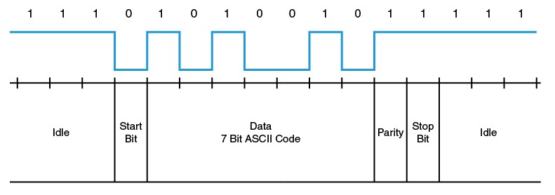
(CompactDAQ/CompactRIO) Some cDAQ and cRIO devices include various serial connections, including RS-232 and RS-485 ports, to communicate with other hardware. These are sometimes referred to as EIA-232 or EIA-485 ports. Serial communications consists of packets of information that include data bits, stop bits, and a parity bit. Data bits transmit information, and stop bits tell the receiving device when the information ends. Parity is a type of error checking that counts the number of 1-bits to make sure they are either even or odd. The parity bit can also be set to always be 1 (mark) or always 0 (space). See the referenced documents for pinouts and more details on serial communication.
Note that C Series modules use a 15-pin DSUB to connect to the chassis, but slot connectors on the backplane can not be used for general serial communications.
The NI cRIO-9068 has both an RS-232 and an RS-485 port. They operate at a maximum baud rate of 230,400 bps.
(CompactDAQ/CompactRIO) Some cDAQ and cRIO devices feature WiFi capability, for communication over a wireless LAN. The Wireless section describes the different wireless configurations available. Wireless devices can be configured for use with a traditional infrastructure wireless network. Some devices support wireless ad-hoc communication, while others do not. See the device user manual for an explanation of how to connect to a wireless network. It is also important to consider physical limitations. For instance, large distances may reduce your connection reliability and data throughput.
The cDAQ-9191 is a single-slot wireless chassis supporting traditional and ad-hoc modes over IEEE 802.11b or 802.11g and common security and authentication protocols, such as WEP, WPA and EAP.
(CompactDAQ/CompactRIO) The cDAQ and cRIO platforms are rugged systems designed to be used in a variety of industrial environments. These specifications describe the conditions that cDAQ and cRIO are guaranteed to work in. Modules and backplanes are rated separately, so verify that all components of your system meet the specifications for your environment.
The cDAQ-9174 has an operating temperature range of -20 °C to 55°C, and a maximum altitude of 5,000 m. If operated at a temperature below 0 °C, verify that your power supply is also rated for that temperature range.
(CompactDAQ/CompactRIO) For more information about NI's commitment to design and manufacture products in an environmentally responsible manner, visit ni.com/environment.
(CompactDAQ/CompactRIO) A hazardous location is an environment that contains potentially flammable or explosive material in the surrounding atmosphere. In North America, the class describes the nature of flammable material (e.g. gas, dust, etc.), the division describes what conditions the hazardous materials may exist under (normal or abnormal), and the group describes the specific type of material present (e.g. acetylene, hydrogen, etc.). Consult your device's user manual or getting started guide for cautions on operating in hazardous locations.
The cRIO-9068 is certified for various locations, but specifically for UL Class I, Division 2, Group A as well as IECEx IIC. Both of these certifications are for locations where acetylene gas may be present.
(CompactDAQ controllers/CompactRIO) Computer memory comes in two forms: non-volatile and volatile. Volatile memory requires power to maintain data, while non-volatile memory does not. In cDAQ and cRIO controllers, code is deployed to non-volatile solid state drives (SSDs). DRAM is a type of volatile memory, which is used to store program variables and other information.
The cRIO-9068 has 1 GB of non-volatile solid state memory, and 512 MB of volatile DRAM memory.
(CompactDAQ/CompactRIO) Mean time between failure (MTBF) is the average time between failure events for a repairable product. It is the mean number of life units during which all parts of the item perform within their specified limits, during a particular measurement interval under stated conditions. MTBF is a statistical estimate that is commonly used to calculate the probability of success (reliability) or the probability of failure for a product for a duration of operation in a defined environment.
(CompactDAQ controllers/CompactRIO) Each compact controller features a built-in multicore processor that runs an embedded operating system, either a Windows OS or a real-time OS. Windows controllers provide an extensive software ecosystem that supports the LabVIEW for Windows platform, plus a familiar user experience. Real-time controllers offer increased software reliability and features designed to optimize headless operation and long-term deployment.
The cDAQ-9133 supports Windows Embedded Standard 7 and NI Linux Real-Time, while the cRIO-9039 only supports NI Linux Real-Time.
(CompactDAQ/CompactRIO) NI publishes dimensional drawings of most products that can be used to check clearance prior to purchasing a device or creating a model of the system being created. Physical characteristics also describe the wiring requirements for terminal connections.
(CompactDAQ/CompactRIO) It is important to know the power requirements of your system so that the correct amount of power can be sourced. NI sells power supplies that meet the recommended specifications, but you may use a third party or custom power supply as needed. Make sure that your power supply is suited for your environment, especially in hazardous or rugged conditions. Some C Series modules have additional power requirements separate from the backplane.
The cDAQ-9178 requires a National Electric Code (NEC) Class 2 power source, and consumes at most 15 W, including 1 W drawn by each module in a fully populated system.
(CompactDAQ controllers/CompactRIO) The processor, or CPU, is the computational and control unit of a computer that interprets and executes instructions. High-performance cDAQ and cRIO Controllers have onboard processors that provide more computational power for complex measurement or control applications.
The cDAQ-9133 features an Intel Atom E3825.
(cRIO) Field-programmable gate arrays (FPGAs) are reprogrammable silicon chips that connect processing logic to I/O blocks. They consist of various components including:
The cRIO-9068 uses a Xilinx Zynq 7020 FPGA. In comparison, the cRIO-9039 uses a Xilinx Kintex-7 7K325T, which has a greater capacity.
(CompactDAQ/CompactRIO) cDAQ and cRIO chassis are tested and in compliance with various standards, which are listed in the three sections of our specifications manuals. For more information on any standard, visit ni.com/certifications.
You can view the compliance specifications for the cDAQ-9178 by using the certifications search: NI cDAQ-9178 - Product Certification.
(CompactDAQ/CompactRIO) Connections to cDAQ and cRIO chassis are rated for various categories of voltages. Measurement Category CAT O, previously known as Measurement Category CAT I, is for measurements of loads, devices, or circuits that are not directly connected to MAINs, and are isolated. Measurement Category CAT II is for measurements that could be connected to MAINs or are not isolated from MAINs. For C Series Modules, their safety voltage ratings are for the specific connection (e.g. RS-485 Serial Port, etc.), so modules with high voltage ratings can be used in any chassis.
Safely connect up to 30 V (Measurement Category I) across the V terminal and C terminal on the cDAQ-9188.
(CompactDAQ/CompactRIO) cDAQ and cRIO chassis are tested to specific industry standards to ensure that stated accuracy per the specifications and device integrity is maintained over the stated shock and vibe specifications. It is important not to exceed these specified values to ensure correct and accurate operation of the device. All cRIO and cDAQ chassis, as well as C Series Modules, are tested for the same shock and vibration standards. However, meeting these specifications may require certain mounting or connection procedures, which are explained in your chassis' user manual.
In order to meet the shock and vibration specifications for the cDAQ-9178, you must panel mount the system, use ferrules on the ends of terminal lines, and use an NI locking USB cable.