Designing Distributed TSN Ethernet-Based Measurement Systems
Overview
Contents
- What Is Time Sensitive Networking?
- What Is IEEE 802.1AS?
- Selecting a Topology
- Selecting an IP Address Mechanism
- Adding Reliability Into Your Distributed TSN Ethernet-Based Measurement System
- NI Hardware Options for Your TSN Ethernet-Based Measurement System
- Next Steps
What Is Time Sensitive Networking?
TSN is the evolution of standard Ethernet—specifically the IEEE 802.1 standard. TSN provides a mechanism for time synchronization of devices using packet transfer over Ethernet, the capability to use the coordinated time to schedule cyclic packet transmission, and a standard set of parameters for configuration of all the network elements. TSN Ethernet-based measurement systems that require correlated sensor readings from multiple locations around the device use the time synchronization element of TSN. TSN synchronization is provided through the IEEE 802.1AS standard.
What Is IEEE 802.1AS?
IEEE 802.1AS is an IEEE 1588 profile that provides a common notion of time on all nodes within the IEEE 802.1AS subnet. The synchronization of multiple devices uses packet-based communication and is possible over long distances without signal propagation delay impact. I/O synchronization on devices using this profile is less than 1 μs, but this can be greatly reduced to the hundreds of nanoseconds range, depending on the configuration of the system. For two end stations to synchronize, there must be a path between them with IEEE 802.1AS-compliant switches. If such a path exists, it is automatically detected and used. CompactRIO Controllers with NI-DAQmx are TSN-enabled controllers and the cDAQ-9185/9189 and FieldDAQ devices contain an integrated switch that is IEEE 802.1AS-compliant, so they can synchronize when connected directly or with an external IEEE 802.1AS-compliant network infrastructure.
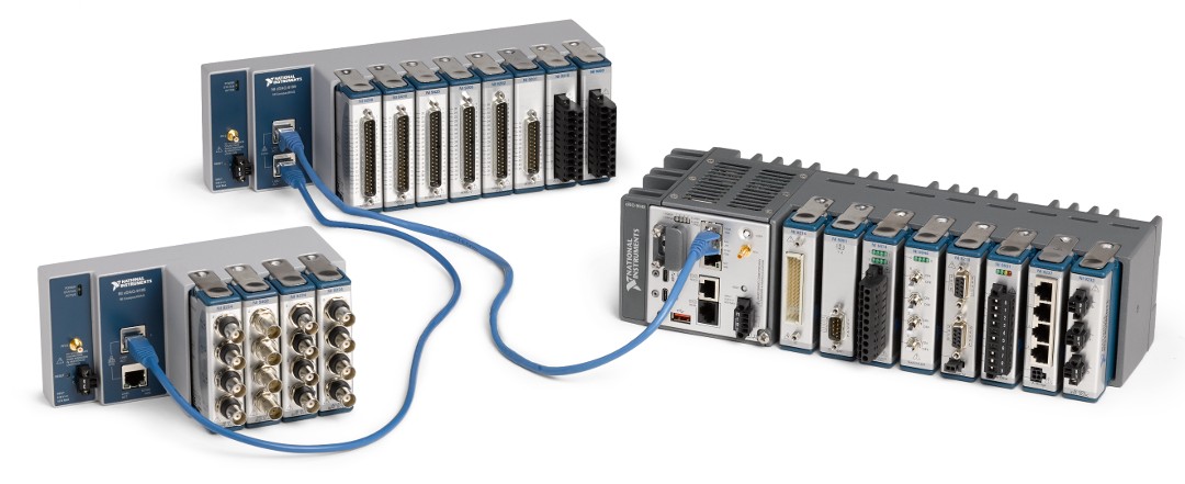
Figure 1. CompactRIO Controllers that support NI-DAQmx and the cDAQ-9185/9189 are used with IEEE 802.1AS-compliant networks.
Selecting a Topology
A critical step in designing a distributed TSN Ethernet-based measurement system is to decide which topology to use for the application. The IEEE 802.1AS profile compensates for the cable length between devices, so you can focus on the advantages and disadvantages each of the topologies deliver to your specific application or create a hybrid topology to best suite your application’s need. Three common topology options for measurement systems include line, ring, and star.
Line Topology
In a line topology, also known as daisy chaining, the host communicates directly with all the devices in the system through one bus line. The line topology is the simplest and least expensive to implement. However, this topology is practical only with devices that have an integrated Ethernet switch. Each device in the topology can be up to 100 m from the previous device, which gives this topology the ability to span vast distances without too much complexity. Make sure to check your device’s specifications document for any limitation in hop length.
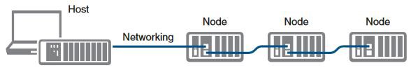
Figure 2. Line Topology.
Here is a list of advantages and disadvantages associated with a line topology:
- Advantages
- The topology is simple and inexpensive to install, add devices to the system, and troubleshoot.
- The topology does not require an external switch to be integrated when the measurement device contains an integrated switch.
- The topology can span long distances with the simplistic design of needing only a single line of devices connected to each other.
- Disadvantages
- Any device in the line that loses power or has a failure disrupts the network communication of all devices downstream in the topology.
- Any Ethernet cable failure and/or improper cable termination disrupts the network communication of all devices downstream in the topology.
- The network and synchronization performance are affected as this topology grows to a massive number of devices.
Ring Topology
In a ring topology, the host communicates with all the nodes through the most effective path. You must use an external switch in a ring topology to complete the loop from the simpler line topology. This redundant connection is exploited automatically to improve data movement and synchronization (if the switch is IEEE 802.1AS-compliant).
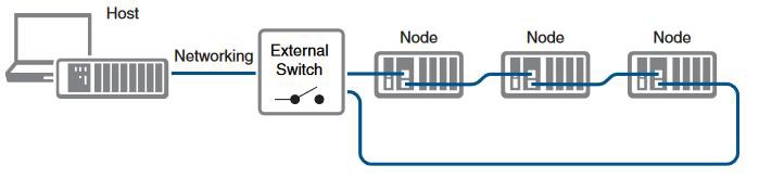
Figure 3. Ring Topology.
To take advantage of the benefits of this topology, you must configure the network properly with switches that are compliant with the required protocols. Switches must be IEEE 802.1Q-compliant to support the Rapid Spanning Tree Protocol (RSTP) as well as IEEE 802.1AS-compliant to support TSN synchronization. However, with this topology, you can have the entire topology support the RSTP specification, ensuring the best path for the data, but only have a subsection of the topology support the IEEE 802.1AS profile as seen in Figure 3 . Keep in mind that if a link between two of the devices that support IEEE 802.1AS is broken, the synchronization data communication is disrupted.
Here is a list of advantages and disadvantages associated with a ring topology:
- Advantages
- The topology is simple to install.
- The network communication is not disrupted if any single Ethernet cable fails (however, this can impact the synchronization communication if all the switches on the topology are noncompliant with the synchronization profile).
- The addition of devices into the topology does not affect the performance as much as the line topology.
- Disadvantages
- Network traffic patterns can make troubleshooting more difficult than the line topology, because the data is not looking for the best path to take back to the host.
- The topology requires an additional switch (compared to the line topology) to complete the loop.
- The topology requires all the devices on the network have a switch.
Star Topology
In a star topology, the host communicates directly with each device on the network through an external switch. Devices can individually connect directly to the switch instead of needing to be connected through each other in lines. To achieve TSN synchronization throughout the star topology, all the devices and switches on the network must be compliant with the IEEE 802.1AS protocol. However, if all the devices on the network have a switch built in, it is possible to add redundant links from each device back to the switch allowing the data to find the best path to the host. With this redundant connection, communication is not disrupted from a single cable failure at each device coming off the main additional switch. To take advantage of the network finding the best path back, all the devices on the network need to be 802.1Q-compliant to support RSTP.
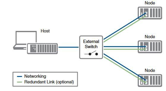
Figure 4. Star Topology.
Here is a list of advantages and disadvantages associated with a star topology:
- Advantages
- The topology is simple to install, add devices, and troubleshoot.
- End points can be integrated to directly communicate with the host.
- The addition of devices on the network affects network performance less than the other topologies.
- Network communication with other devices on the network is not disrupted with the failure of or loss of power to a single device off the switch.
- Network communication is not disrupted from any single Ethernet cable failure when using a redundant link for all the devices off the switch.
- Disadvantages
- The topology requires an external switch for the host to directly communicate with each device on the network.
- A switch connects all the devices back to the host, so this topology is restricted in the distance that it can cover between all device
Advanced/Hybrid Topology
You can mix and match the three main topologies for distributed TSN Ethernet-based measurement systems to create a hybrid topology that blends the strengths of each to fit your application’s need. A tree topology is a common hybrid that integrates aspects of the line and star topologies. You can break up different groups of devices into smaller star topologies along a single line topology back to the host. By having sections of different star topologies, you can manage those as individual subsystems on your network to complete different tasks. For instance, by having the IEEE 802.1AS profile run on one of the subsystems, you can have those devices take advantage of the TSN synchronization while another subsystem is being used to connect additional Ethernet devices for non-measurement tasks. By blending these topologies, you also blend some of the disadvantages. With the tree topology, if the main line topology link fails, network communication for all the star subsystems downstream are disrupted.
When it comes to selecting a topology for your distributed TSN Ethernet-based measurement system, there is no single answer. You must weigh the advantages and disadvantages of each type of topology to decide which can meet the specific needs of the application you are designing the system for.
Selecting an IP Address Mechanism
To communicate on the network, Ethernet devices must obtain an IP address that is used as its identification. There are three common ways to accomplish this: DHCP, link-local, or manual assignment of a static IP address. Most Ethernet-based devices issue a DHCP to obtain an IP address. If the devices are connected to a network with a DHCP server, the devices receive an available address from it. If there is no DHCP server on the network, the devices time-out, usually within a few seconds, and respond by attempting to obtain a link-local address. This process requires scanning the network for an available address, which can take significant time. The fastest and most reliable way to configure the IP address of an end station is to manually assign it, which requires care to avoid assigning the same address to two devices.
For a host PC to communicate with the device, the PC’s network connection must be configured correctly, and the IP address of the target device known. If the PC and device are both configured by DHCP, this normally occurs automatically. When the device uses link-local or a manually assigned address, additional steps must be taken to ensure the PC is configured correctly to reach the device.
Adding Reliability Into Your Distributed TSN Ethernet-Based Measurement System
You want to ensure that your distributed application—as with any application—can handle an unexpected failure of a device or connection. When implementing a distributed system, the measurement devices typically are located within the same test environment as the device that is being measured—as close to the sensors as possible. This often means that the measurement device can be exposed to harsh and demanding conditions where standard desktop equipment might give inaccurate data or fail entirely. Ensuring that your signal conditioning and DAQ equipment can survive the test environment helps guarantee that you get accurate data the first time and eliminate the need for costly retests. Possible requirements for your system could include extreme temperature ranges for product validation testing, shock and vibration survivability (if the system is to be mounted directly to a machine), or hazardous location certifications to ensure the system can safely operate in marine or explosive environments.
Although it is possible to design enclosures for any DAQ system to meet various ruggedness requirements, it is often cheaper to purchase a system already tested and certified to survive the conditions. Design, materials, test, and compliance costs can quickly add up, in addition to the time to properly go through these steps, in developing and integrating your own ruggedness solutions. Vendors can amortize these costs over thousands of units and offer the same benefits at a lower price.
Learn more about ruggedness and how to choose the right system for your environment.
Link Reliability
Ensuring that the measurement devices can withstand the test environments in which they are placed is one consideration, but another is what happens if a connection between these devices fails or becomes damaged. Adding a redundant link to your measurement system topology allows the network to determine the best path for the data to flow. By implementing a redundant link in a ring or star topology, where all the devices on the network are both IEEE 802.1AS- and IEEE 802.1Q-compliant and configured to implement both protocols, the network automatically reroutes the data through the next available route if a single connection in the network is damaged or fails.
This process usually takes two to 15 seconds, depending on the link that was broken or restored (though the exact time depends on the network configuration). Applications must allow for this time by ensuring enough buffering is available on the sender and that the receiver can tolerate the temporary interruption of data and properly handle any application-level areas related to those interruptions.
System Reliability
Additionally, there are a few failures that are not physical failures of the hardware or connections caused by damage, but can still cause your measurement application to fail. These failures include a power cycle or software reset on a device running in your network or a device that is physically removed or added to the network while the measurement application is running. Below are some of the ways you can allow your measurement application to account and adjust for these failures.
One source of error is loss of network synchronization. In IEEE 802.1AS, a reference clock, referred to as the grand master (GM) clock, is selected automatically through an election algorithm. The election is based on clock quality, traceability, priority, and, if necessary, the MAC address of the device (the MAC address always determines the GM for a set of identical devices). This election is repeated every time a device is added to or removed from the set of IEEE 802.1AS-connected devices, such as when they are reset. If the GM resets, or the path to the GM is broken, then a new GM is chosen. If the GM changes during operation, it cannot be assumed that the operation is still synchronized as intended, so NI-DAQmx issues a “sync lock lost” error.
Another source of error is loss of synchronization paths. The RSTP and IEEE 802.1AS mechanisms operate independently and can use different links. This means it is possible to break synchronization without breaking data transfer.
NI-DAQmx has features that allow applications to handle these and other errors. Applications that are not sensitive to temporary loss of synchronization should set the “stop on sync lost” property to false. These applications can check the “sync lost” property to detect if synchronization was lost. Generally, applications with high reliability requirements should use a single task per chassis. This ensures that device failures are as isolated as possible and minimizes the number of affected channels in case of a failure or temporary removal of any nodes in the system.
In the case that you are unable to recover from a system failure with your measurement application or if a connection in the network fails or becomes damaged where the network is unable to find a path for the data, it is a best practice to have a contingency plan in place to ensure the system is placed in a known safe state. Using a hardware watchdog timer is one way of providing a fail-safe mechanism to your system. The hardware watchdog timer is used to monitor and identify if the system is operating correctly. If the system is not operating as intended, the system is placed in a safe state. If your measurement device includes a hardware watchdog timer, you can configure it to take over the output channels on an unwanted event to avoid damage to the system.
Learn more about hardware watchdog timers and how to implement them in NI-DAQmx.
NI Hardware Options for Your TSN Ethernet-Based Measurement System
NI offers a wide variety of platforms and products that you can use to build distributed TSN Ethernet-based measurement systems. The range of TSN-enabled products includes:
- CompactDAQ - Modular chassis designed for easy deployment and operation
- CompactRIO - Highly flexible embedded controllers featuring integrated Real-Time OS and FPGA access
- FieldDAQ - Rugged, easy to use measurement hardware with integrated signal conditioning
With the span of capability across these platforms and products, there is an NI solution that can help you meet all your specific distributed measurement application’s needs.
CompactDAQ
CompactDAQ is a mixed-measurement modular platform with built-in signal conditioning and a wide breadth of I/O options. You can create an optimized system for your distributed measurement needs without paying for unneeded functionality but with the flexibility to adapt to changing requirements over time. The cDAQ-9185 and cDAQ-9189 chassis feature an integrated switch that is compliant with both IEEE 802.1AS for TSN synchronization and IEEE 802.1Q for RSTP implementation, allowing you to integrate them in the ideal topology for your application. These chassis are built for ruggedness to meet the needs of demanding test environments; they feature an operating temperature range of -40 °C to 70 °C, up to 50 g of shock, a variety of safety and environmental certifications, and an integrated hardware watchdog timer to provide the fail-safe mechanism as a contingency plan for your application.
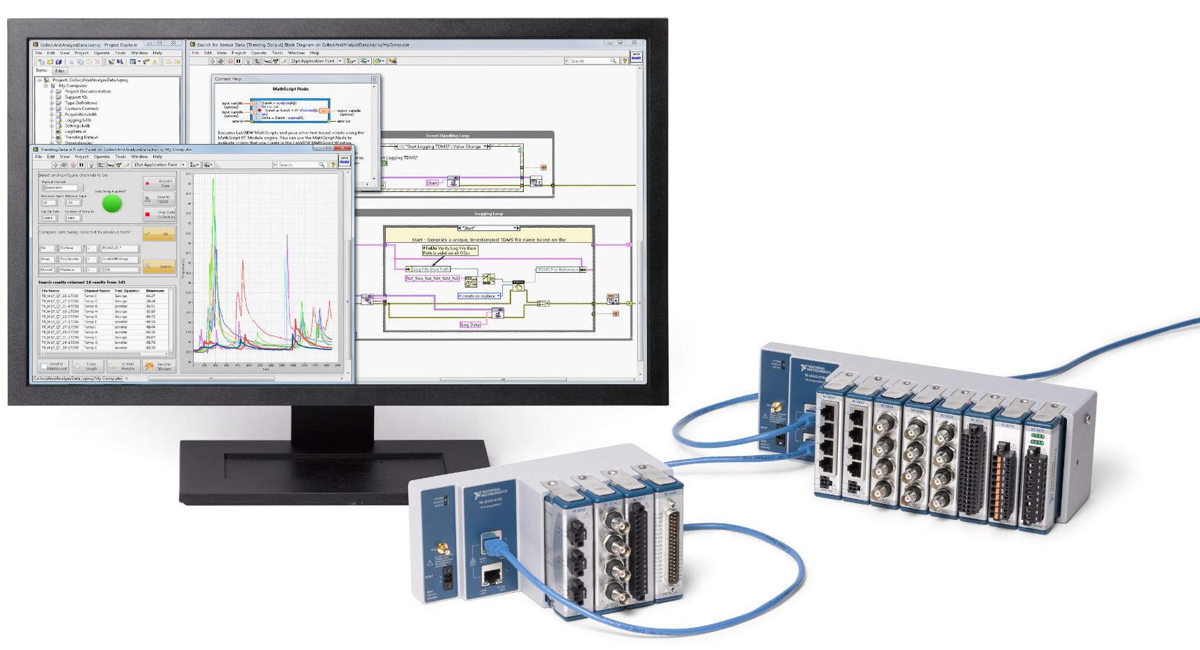
Figure 5. CompactDAQ is a portable, rugged DAQ platform that integrates connectivity and signal conditioning into modular I/O for directly interfacing to any sensor or signal.
CompactRIO
CompactRIO hardware combines an embedded real-time processor, a high-performance FPGA, and a wide breadth of I/O options that you can program using NI-DAQmx or the LabVIEW FPGA Module. Each I/O module is either connected directly to the FPGA: providing low-level customization of timing and I/O signal processing, or routed to the real-time processor: using the intuitive DAQmx API for measurements and control. CompactRIO controllers are TSN-enabled: delivering the TSN technology to an embedded real-time controller. These controllers can not only take distributed synchronized measurements with the same C Series modules as CompactDAQ using the IEEE 802.1AS profile but can also serve as the distributed measurement system host running the NI Linux Real-Time OS.
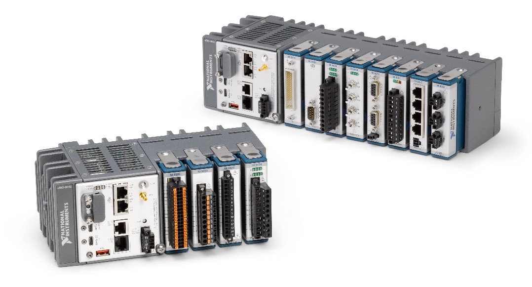
Figure 6. CompactRIO with NI-DAQmx brings software experiences together by combining NI Linux Real-Time, NI-DAQmx, and LabVIEW FPGA.
FieldDAQ
FieldDAQ combines sensor-specific signal conditioning, connectivity, and digitization to directly interface to common sensors and signals such as thermocouples, strain gages, and more. With FieldDAQ, you can take accurate measurements as close to your sensor as possible, under a full range of environmental conditions. FieldDAQ devices have an ingress protection rating up to IP67 (IP65/IP66/IP67), making these devices dust-proof and resistant to water submersion and jet spray downs. These devices can operate in -40 °C to 85 °C environments while dissipating heat through passive cooling, eliminating fragile moving parts such as fans. FieldDAQ uses standard, industrial connectors to prevent cables from detaching during operation even up to 100 g shock and 10 grms conditions. FieldDAQ is built on National Instruments open, software-centric platform and expands the NI TSN product ecosystem. You can customize the setup of your system by effortlessly connecting and synchronizing FieldDAQ with other TSN products, such as CompactDAQ and CompactRIO, and how you acquire, visualize, and analyze real-world signals to make data-driven decisions.
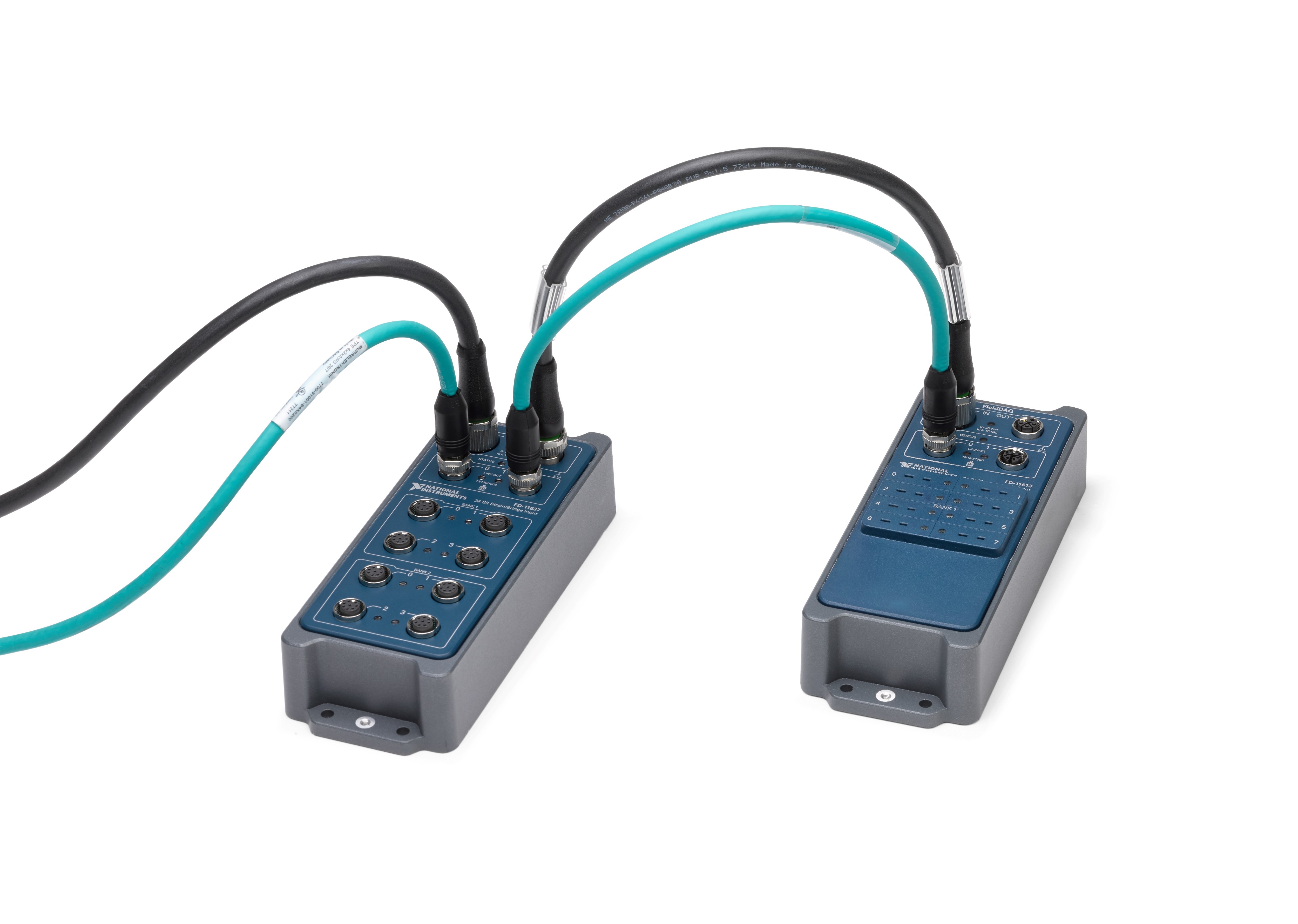
Figure 7. FieldDAQ is designed for the harsh environments of any application.
Hardware Built for Distributed Measurements
When designing and implementing distributed TSN Ethernet-based measurement systems, there are several ways to ensure you have an efficient and reliable system to meet the application’s needs. Some larger topics to investigate include selecting an ideal topology for the application and selecting hardware that not only meets the needs of the ideal topology but also withstands the test environment and provides additional reliability when needed. When selecting hardware to endure these factors, you can save time, money, and frustration by using hardware, such as CompactDAQ, CompactRIO, and FieldDAQ that is used to build high-quality distributed measurement systems.
Next Steps
The registered trademark Linux® is used pursuant to a sublicense from LMI, the exclusive licensee of Linus Torvalds, owner of the mark on a worldwide basis.