Altran and NI Demonstrate ADAS HIL With Sensor Fusion
Overview
As vehicles move toward autonomous capability, there is a rising need for hardware-in-the loop (HIL) testing to validate and verify the functionality of advanced driver assistance systems (ADAS), which are anticipated to play a central role in autonomous driving. This white paper gives an overview of the ADAS HIL with sensor fusion concept, shares main takeaways from initial research efforts, and highlights key system-level elements used to implement the application.
Contents
- What is Sensor Fusion
- When is Sensor Fusion Used?
- ADAS HIL Test Environment Suite (AHTES)
- Component-Level Overview
- Conclusion
- Resources
What is Sensor Fusion
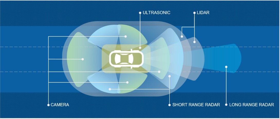
Today, many cars have multiple ADAS based on different sensors like radar, cameras, LIDAR, or ultrasound. Historically, each of these sensors perform a specific function and, only in rare cases, share information with each other. The amount of information that the driver receives is proportional to the number of sensors in use. If sensor data is sufficient and communication is in place, smart algorithms can be used to create an autonomous system.
Sensor fusion is the mixture of information from various sensors, which provides a clearer view of the surrounding environment. This is a necessary condition to move toward more reliable safety functionality and more effective autonomous driving systems.
Figure 1. A “View” of the Environment Surrounding a Car
When is Sensor Fusion Used?
Sensor fusion can be relevant with all types of sensors. A typical example is the fusion of information provided by a front camera and a front radar. A camera that works in the visible spectrum has problems in several conditions like rain, dense fog, sun glare, and absence of light, but has high reliability when recognizing colors (for example, road markings). Radar, even at low resolution, is useful for detecting distance and is not sensitive to environmental conditions.
Typical ADAS functions that use the sensor fusion of front camera and radar include:
- Adaptive Cruise Control (ACC)—This cruise control system for the vehicle adapts speed to traffic conditions. The speed is reduced when the distance from the vehicle ahead drops below the safety threshold. When the road is clear or the distance to the next vehicle is acceptable, the ACC accelerates the vehicle back to the set speed.
- Autonomous Emergency Braking (AEB)—This controls the braking system by reducing the speed in the case of a certain collision or by otherwise alerting the driver in critical situations.
ADAS HIL Test Environment Suite (AHTES)
For the validation of complex systems, it is necessary to set up an appropriate test environment that effectively stimulates the sensors to verify the behavior of the vehicle under real-world conditions.
Altran Italia has integrated an innovative radar object simulator based on NI technologies and a 3D virtual road scenario simulator into an HIL set up to produce a scenario-based tester that fully synchronizes camera and radar data to validate sensor fusion algorithms.
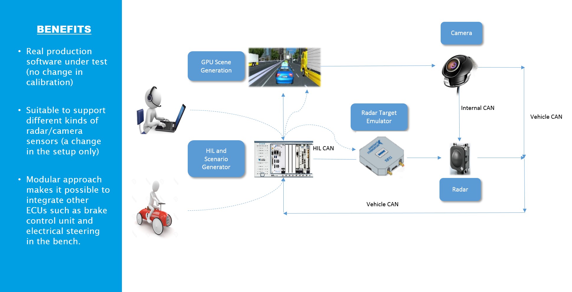
Figure 2. ALTRAN-NI ADAS HIL Test Solution
The 3D scenario is based on the Unity 3D Graphic Engine, a cross platform game engine by Unity Technologies, and is fully configurable allowing customization of parameters such as number of lanes, lighting conditions, and track type. A variety of other graphic model environments also exist on the market and could be used similarly such as IPG Carmaker and TASS PreScan.
The graphic engine reproduces the scene from the viewpoint of a camera placed on the windshield of a vehicle. The scene can be modified based on the height from the ground and the camera’s field of view. It is also possible to show an obstacle (for example, a vehicle) at a set distance from the camera at a defined speed.
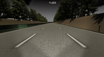
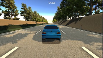
Figure 3. Unity Graphic Engine Scenario
For the vehicle control, the graphic engine receives the position of the brake pedals and throttle in addition to the steering angle. A PXI System acquires this data in addition to signals from the steering wheel and pedals (Logitech G29). The dynamic vehicle model is integrated within the graphics engine and is highly configurable.
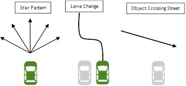
Figure 4. Standard Maneuvers
Per the selected obstacle scenario (with some examples above as a starting point), the graphic engine outputs the vehicle speed as well as information needed by the VRTS to produce an RF signal. All input/output information is exchanged with the PXI through a proprietary protocol and can be changed as needed.
A CAN communication with PXI-8512/2 was used in this setup to retrieve information from the scenario generator about radar targets (distance, radar cross sections, angle of arrival, and speed). The PXI-8512/2 is a two-port high-speed CAN/CAN-FD interface for PXI Systems used for transmitting and receiving CAN bus frames at 1 Mbit/s. The information is sent to the Obstacle Generator only if the information about the targets changes between consecutive readings.
In addition to sending the data to the Obstacle Simulator and acquiring pedal and steering signals, PXI also emulates the CAN messages sent to and from the radar and camera over a private vehicle network.
CAN messages are synchronized with the 3D virtual scenario and RF Target Generator to produce the correct environment for validating modern camera and radar data.
Component-Level Overview
Here are brief descriptions of each system component and communications connection/bus:
- Radar Engine Control Unit (ECU)—The main task of the radar sensor is to detect objects and measure their velocity and position relative to the movement of the host radar-equipped vehicle. The radar sensor is a monostatic multimodal radar and uses the 76 GHz frequency band with six fixed radar antennas. The sensor can detect other vehicles at roughly 250 meters. The radar is equipped with a heated lens that ensures full sensor availability, even in poor weather conditions such as snow and ice. The relative speed of objects is measured using the Doppler effect—change in frequency between the reflected and transmitted signals—and distance to the object can be determined by the time lag.
The ECU handles the sensor fusion with the information from the camera and is responsible for functions such as ACC and AEB.
- Camera ECU—The Camera ECU acquires images of the surrounding environment and provides several pieces of information such as distance from lane lines and other objects. This information is sent to the Radar ECU for sensor fusion, but in some cases (for example, road signs and lane keeping), the Camera ECU works alone. In this case, it sends CAN messages on the Vehicular CAN.
- Video Scenario Generation—Video Scenario Generation is a simulator that includes a vehicle system that receives input from PXI-8512/2 through CAN communication and transmits info about the simulated environment. Radar data such as distance, radar cross section (RCS), angle of arrival, and speed is generated during simulation and is calculated in real time based on the video scenario. Through the control panel in the second screen, it is possible to handle connection with PXI-8521/2, change weather conditions, adjust radar position, and spawn a new vehicle with defined speed and distance.
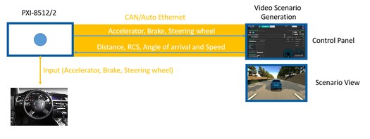
Figure 5. Vehicle Communication Emulation
This simulator has been developed using the Unity 3D Graphic Engine, a cross platform game engine by Unity Technologies. Using a modularized approach, the video scenario can be easily integrated with every third-party platform, plugin, or device like the Logitech G29 shown in the previous image.
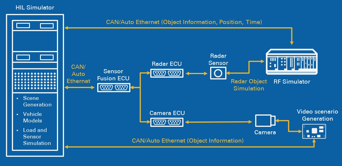
Figure 6. ADAS HIL Test Environment
The radar object simulator is used in the HIL system for test and measurements. The flexibility, modularity, and scalability of the NI system enables users to easily integrate it with other I/O as part of a comprehensive HIL tester for radar design and test applications and to use the same system for both target emulation and radar device measurements, lowering the cost of device and system test.
The system is capable of:
- RF measurements for sensor performance verification
- Signal analysis: equivalent isotropically radiated power ( EIRP), noise, beam width, and frequency
- Chirp analysis: linearity, overshoot, recording, and tagging
- Radar target simulator for sensor functional verification
- Single and multiple targets
- Fixed and variable distance
- Multiple object scenarios (distance, velocity, size, and angle of arrival)
- Customizable target scenarios
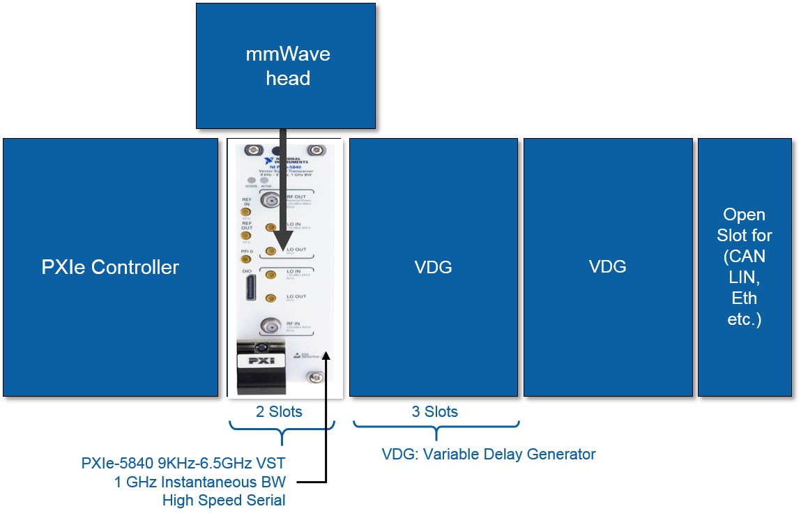
Figure 7. Two-Target, One-Angle System Architecture
In Figure 7, the setup with one PXIe-5840 vector signal transceiver and one mmWave head can generate two targets with the same angle of arrival. Thanks to the PXI platform flexibility, the system could be easily extended to cover multiple targets with multiples angles of arrival. In Figure 8, the configuration with four PXIe-5840 devices and four mmWave heads can simulate up to eight different targets with four angles of arrival.
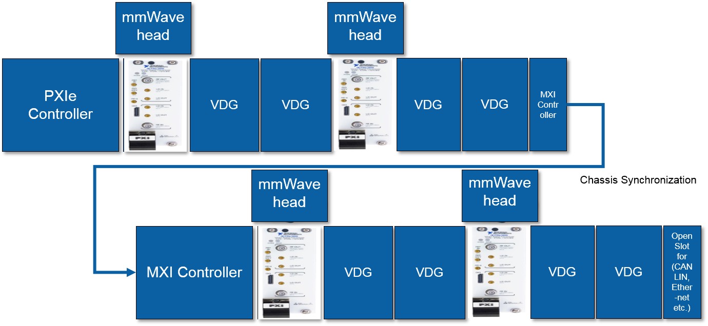
Figure 8. Eight-Target, Four-Angle System Architecture
The radar object simulator chassis can be integrated with standard automotive bus communication (CAN or LIN) and other types of industrial communications required for the HIL system. The modularity of the solution allows car makers to test complex real-world scenarios with the possibility of handling multiple angles of arrival. Standard maneuvers provided by the New Car Assessment Program (NCAP) guidelines can be tested automatically, saving test time and effort.
Conclusion
Altran has demonstrated how it is now feasible to perform laboratory validation of systems like RADAR and cameras that work stand alone or integrated.
Both components are safety critical, so the ability to test in the lab before conducting vehicle tests is a crucial step.
Validating in this manner offers the following advantages:
- Ability to anticipate validation at a stage prior to availability of the vehicle to allow corrective actions that otherwise would come too late
- Overall development time is greatly reduced because tests can be started before the vehicle is available
- Development costs are reduced by having a system that can work all day, seven days a week
- No-regression tests can be carried out in greatly reduced time and with minimal cost compared to using the assembled vehicle
Although ADAS HIL Test Environment Suite was created by Altran based on NI software and hardware for verification and validation, its use is not limited to these scopes; in fact, it can be used to calibrate ECUs to discover parameters for vehicle tests.
ADAS can be fully integrated with other NI hardware products for HIL such as switch load signal conditioning (SLSC) hardware for standardization and routing of signals, switching loads, and signal conditioning. With VeriStand real-time test software, each component can be integrated in a framework that can interact with real-time HIL systems.
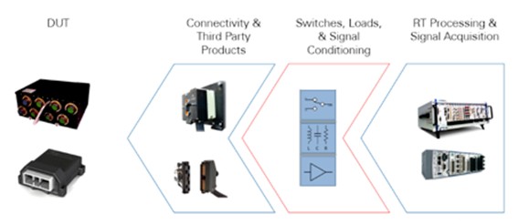
Figure 9. How SLSC Fits Into an HIL System
NI has also extended its platform with an ecosystem of industry-leading partners in the connected car and advanced vehicle technology space such as infotainment test, battery management system test, V2X communication, and vehicle noise and vibration analysis.
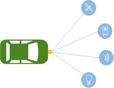
Figure 10. VX2, Lidar, and GNSS for the Connected Car
Authors
Mario Amoruso (National Instruments)
Stefano Caiola (National Instruments)
Giuseppe Doronzo (Altran Italia)
Marino Difino (Altran Italia)
Reviewers
Ram Mirwani (National Instruments)
Matteo Moriotti (Altran Italia)
Davide Palandella (National Instruments)
Resources
Using the SLSC Architecture to Add Additional Elements to the Signal Path of a Test System
About Altran
As a global leader in engineering and R&D (ER&D) services, Altran offers its clients a new way to innovate by developing the products and services of tomorrow. Altran works alongside its clients on every link in the value chain of their project, from conception to industrialization.
For over 30 years, the group has provided its expertise to key players in the aerospace, automotive, defense, energy, finance, life sciences, railway, and telecoms sectors among others.
In 2016, the Altran group generated revenues of €2,120bn. With a headcount of more than 30,000 employees, Altran is in more than 20 countries.
Altran has been present in Italy since 1996 and currently employs about 2,800 people. It is headquartered in Rome and is in much of the country: Genoa, Turin, Milan, Trieste, Verona, Padua, Bologna, Modena, Pisa, Florence, Naples, Pomigliano, and Brindisi. In 2015, it generated sales of 208 million €.
altran.com and altran.it