CAN Physical Layer and Termination Guide
Overview
This document presents an overview of the various physical layers for controller area networks. It details which NI CAN products support which layers and how to correctly terminate each layer.
Contents
- Introduction
- High-Speed/FD CAN Overview
- Low-Speed/Fault-Tolerant CAN Overview
- Single-Wire CAN Overview
- Using Other Transceivers With NI CAN Interfaces
- Additional Resources
Introduction
Controller area networks are used in a wide variety of embedded applications ranging from small medical devices to large earth-moving equipment. To best take advantage of the cost and performance of CAN across these different applications while maintaining software and functional compatibility for tools, you can use a variety of physical layers optimized for different standards. The physical layer of a CAN implementation dictates the cabling types, electrical signal levels, and termination scheme you use. The portion of a CAN interface that connects a CAN controller to the network is called a transceiver.
You can access all CAN networks from the same tools at the software level regardless of the physical layer. The only difference between CAN networks is the transceiver used. PC CAN interface vendors implement these various transceivers through three methods:
- User-interchangeable transceivers that are installed in a generic CAN interface, with the user adapting the interface to a particular network
- Built-in transceivers per interface, with a dedicated hardware interface per physical layer
- Multiple software-selectable onboard transceivers connected to the network by a relay and switched by the host application
NI CAN interfaces are available as the second and third types, with dedicated interfaces and software-selectable interfaces. In general, software-selectable interfaces are used for applications where the end CAN network is not known and could change, such as a lab or automated test environment. In embedded and dedicated applications for which the end CAN network is known, integrated onboard transceivers save cost and reduce complexity. The three NI CAN platforms are available in the following types:
- NI-XNET PCI, PXI, and C Series CAN: Onboard, software-selectable
- NI USB CAN: Onboard
- CompactRIO CAN: Onboard
High-Speed/FD CAN Overview
High-speed CAN is the most common CAN transceiver. It is used in nearly every production automobile and is required in model year 2008 and later On-Board-Diagnostic (OBD-II) vehicles sold in the USA.
The high-speed CAN layer derives its name from the fastest form of CAN, which allows use of the full standard speed up to 1 Mbit/s. High-speed CAN networks support baud rates from 40 kbit/s to 1 Mbit/s. The most common rate, 500 kbit/s, is used in automotive environments.
The baud rates affect the total allowable length of the network, which ranges from roughly 1 km at 40 kbit/s to 40 m at 1 Mbit/s. The maximum stub length, or length from the central CAN network that nodes can be placed, is also affected. Generally, CAN network stubs should be less than 1 m.
High-speed CAN is specified or required by the following standards:
- ISO-11898-1, -2, -5
- ISO-11783-2
- MilCAN
- CANopen
- DeviceNet
- SAE J1939
- SAE J2284-1, -2, -3,
CAN with Flexible Data-Rate (CAN FD) is the next generation of high-speed CAN communication with evolving standards for higher data rates. NI has enabled speeds up to 8 Mbit/s using the TJA1041 and TJA1043 transceivers through the NI-XNET driver. The overall baud rate for FD networks is the same as high-speed CAN, it is just the data rate that is faster. As transceiver vendors complete qualifications for CAN FD speeds, NI will update our documentation as necessary.
High-Speed/FD CAN Termination
For high-speed/FD CAN, both ends of the pair of signal wires (CAN_H and CAN_L) must be terminated. This is because communication flows both ways on the CAN bus. CAN_L is pin 2 and CAN_H is pin 7 on the standard 9-pin D-SUB connector. The termination resistors on a cable should match the nominal impedance of the cable. ISO 11898 requires a cable with a nominal impedance of 120 Ω; therefore, you should use 120 Ω resistors for termination. If you place multiple devices along the cable, only the devices on the ends of the cable need termination resistors. Figure 1 shows an example of how to terminate a high-speed network.
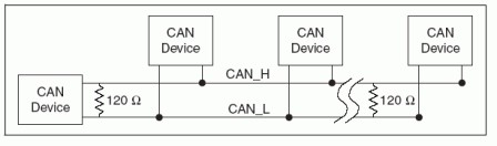
Figure 1. Terminating a High-Speed CAN Network
High-Speed/FD CAN Cables and Accessories
NI-XNET high-speed/FD and software-selectable/FD CAN interfaces have onboard software-selectable termination. This gives you the flexibility to programmatically add termination to the network whenever needed without changing cables.
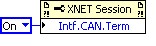
Figure 2. NI-XNET Software-Selectable Termination
NI also offers terminated and nonterminated CAN cables for connecting NI high-speed/FD CAN interfaces to CAN devices and networks. Legacy NI CAN devices do not have software-selectable termination, so you may need to purchase terminated cables for use with those interfaces.
In general, when connecting a single CAN device to an NI CAN interface, you can programmatically enable termination or use a terminated cable. In the first option, the NI-XNET device connects a 120 Ω resistor between CAN_H and CAN_L using relays. In the case of the terminated cable, it contains one 120 Ω resistor installed on the CAN_H and CAN_L lines in the connector closest to the NI cable part number label.
When connecting multiple CAN devices that already have termination, NI nonterminated cables are recommended.
The NI CAN breakout box offers a switch to enable and disable 120 Ω and 60 Ω termination on a CAN network for maximum flexibility.
Learn more in the NI-XNET Manual or the NI-CAN Hardware and Software Manual.
Low-Speed/Fault-Tolerant CAN Overview
Low-speed/fault-tolerant CAN is designed to withstand opens, shorts, and incorrect loads on one of the CAN data lines, falling back to a single data line when a fault is encountered. To preserve network functionality in a scenario where a data line fails to open, termination resistors are required at each node. These extra fault-tolerance features limit the maximum speed of a low-speed/fault-tolerant CAN network to 125 kbit/s.
Low-speed/fault-tolerant CAN is found in the following specifications:
- ISO-11898-3
- ISO-11992-1
Low-Speed/Fault-Tolerant CAN Termination
For low-speed/fault-tolerant CAN, each device on the network needs a termination resistor for each data line: R(RTH) for CAN_H and R(RTL) for CAN_L. Unlike the high-speed CAN termination, low-speed CAN requires the termination to be on the transceiver rather than on the cable. Determining the Necessary Termination Resistance for the Board can be found in the manual. Figure 3 shows a diagram of termination resistor locations on a low-speed network.
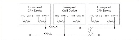
Figure 3. Low-Speed/Fault-Tolerant CAN Termination
Low-Speed CAN Cables and Accessories
Because every node on a low-speed/fault-tolerant CAN network is terminated, NI fault-tolerant CAN interfaces are shipped with onboard termination resistors. The NI-XNET Manual and the NI-CAN Hardware and Software Manual contain instructions for adjusting these resistors if your application requires different values. You should use only nonterminated CAN cables for connecting NI fault-tolerant CAN interfaces to fault-tolerant CAN devices and networks.
Single-Wire CAN Overview
Single-wire CAN is primarily found in specialty automotive applications and emphasizes low cost. Defined in the SAE 2411 specification, single-wire CAN uses only one single-ended CAN data wire as opposed to the differential CAN wires found in most applications. The reduced noise immunity of single-wire CAN limits its speeds to either 33.3 kbit/s or 83.3 kbit/s.
Single-Wire CAN Termination
Single-wire CAN specifies a single 9.09 kΩ resistor for the entire network. NI interfaces featuring single-wire CAN transceivers include a built-in 9.09 kΩ resistor, so no additional resistors are needed.
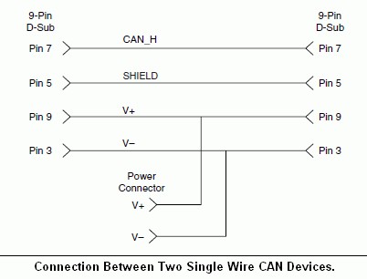
Figure 4. Connection Between Two Single-Wire CAN Devices
Single-wire CAN transceivers are available only on NI-XNET software-selectable PCI and PXI interfaces.
Single-Wire CAN Cables
Because single-wire CAN networks are already terminated, you should use only nonterminated CAN cables for connecting NI single-wire CAN interfaces to single-wire CAN devices and networks. NI fault-tolerant CAN interfaces are shipped with onboard termination resistors. The NI-CAN Hardware and Software Manual contains more information about single-wire CAN on pages 3-16 and 4-20.
Using Other Transceivers With NI CAN Interfaces
Occasionally, CAN applications use a nonstandard or specialty transceiver for a particular application. With NI-CAN software-selectable interfaces, it is possible to bypass the onboard transceivers and connect a custom transceiver to the external connector on the board without modifications to the interface.