From 04:00 PM CDT – 08:00 PM CDT (09:00 PM UTC – 01:00 AM UTC) Tuesday, April 16, ni.com will undergo system upgrades that may result in temporary service interruption.
We appreciate your patience as we improve our online experience.
From 04:00 PM CDT – 08:00 PM CDT (09:00 PM UTC – 01:00 AM UTC) Tuesday, April 16, ni.com will undergo system upgrades that may result in temporary service interruption.
We appreciate your patience as we improve our online experience.
Cascading SCXI modules allows you to combine and apply the functionality of several SCXI modules to an input signal in one data acquisition process. This document provides the steps to install and configure a typical cascaded SCXI module system. For additional information refer to the SCXI-1352 Installation Guide and other NI documents at www.ni.com.
Each SCXI module provides a stage of signal conditioning. For cascading applications, the first stage is defined as the first module through which the input signal passes. The last stage is the last SCXI module through which the signal passes before it is digitized by the analog to digital converter (ADC) on the E Series data acquisition (DAQ) device. The following tables list the supported cascaded SCXI module systems.
Recommended S-series Configurations
| Application | Driver Support | First Stage | Second Stage | Third Stage | Connected DAQ Board |
| Simultaneous Isolated Strain with filtering | DAQmx Only | Two SCXI-1121 | SCXI-1141/2/3 |
--
| S-series |
| Simultaneous Isolation | DAQmx Only | SCXI-1125 or SCXI-1120/D |
--
|
--
| S-series |
| Simultaneous Isolation w/ Programmable Filters | DAQmx Only | SCXI-1120/D | SCXI-1141/2/3 |
--
| S-series |
| Simultaneous Isolated Strain | DAQmx Only | One SCXI-1121 |
--
|
--
| S-series |
Note: Some of the recommended s-series configurations only have a single stage. These solutions are not technically considered cascading solutions, but they are recommended over other comparable cascading solutions for their overall ease of configuration and their cost effectiveness. All SCXI modules that support parallel mode will work with S-series even though they are not shown in this table.
Fully Supported E/M Series Configurations
| Application | Driver Support | First Stage | Second Stage | Third Stage | Connected DAQ Board |
| Simultaneous Isolated Strain | DAQmx, Traditional DAQ | Two SCXI-1121 | SCXI-1140 |
--
| M-series / E-series |
| Simultaneous Isolation | DAQmx, Traditional DAQ | SCXI-1120/D | SCXI-1140 |
--
| M-series / E-series |
| Isolation / Programmable Filters | DAQmx, Traditional DAQ | SCXI-1120/D | SCXI-1141/2/3 |
--
| M-series / E-series |
Partially Supported Configurations
| Application | Driver Support | First Stage | Second Stage | Third Stage | Connected DAQ Board |
| Isolation | Traditional DAQ Only | SCXI-1125 | SCXI-1140 |
--
| E-series |
| Isolation / Programmable Filters | Traditional DAQ Only | SCXI-1125 | SCXI-1141/2/3 |
--
| E-series |
| Simultaneous Filtering | Traditional DAQ Only | SCXI-1141/2/3 | SCXI-1140 |
--
| E-series |
| Isolated Strain | Traditional DAQ Only | Two SCXI-1121 | SCXI-1141/2/3 | SCXI-1140 | E-series |
| Isolation / Programmable Filters | Traditional DAQ Only | SCXI-1120/D | SCXI-1141/2/3 | SCXI-1140 | E-series |
| Isolation / Programmable Filters | Traditional DAQ Only | SCXI-1125 | SCXI-1141//2/3 | SCXI-1140 | E-series |
Note: Partially supported solutions are easy to use and configure in Traditional DAQ, but the accuracy of your data will be degraded because under the typical use case you will be unable to use the calibration constants on any module that isn’t directly connected to the DAQ device. Most of the partially supported solutions have an equivalent supported solution that will enable you to retain full accuracy from all of your SCXI modules.
Signal Conditioning Considerations:
This application uses the isolation of the SCXI-1120 or SCXI-1121 module, then filters the signal using the SCXI-1141 module before acquiring a sample with the E Series DAQ device.
Equipment Needed:
Procedure:
Note: Configure the SCXI-1120 or SCXI-1121 module with gains that keep their output signals within the input range of the SCXI-1141 module. For example, if the input signal range is 1 mV, and the SCXI-112x module is at the default gain setting of 1000, then its output signal is 1 V. This signal is still within the 5 V input range of the SCXI-1141 module. SCXI-1120 and SCXI-1121 gains are set using hardware jumpers. If you need to change the gain jumpers, do so before going on to the next step. You can find detailed instructions for setting these jumpers are in the module user manual.
1. Open Measurement & Automation Explorer.
2. Expand Devices and Interfaces >> NI-DAQmx Devices by clicking the + symbol. You should see the DAQ device listed.
3. Insert a new SCXI chassis by right-clicking over NI-DAQmx Devices and select Create New NI-DAQmx Device…>>NI-DAQmx SCXI Chassis>>select your chassis from the list.
4. A window appears allowing you to select the communicating DAQ device and the chassis address. Select a DAQ device which is cabled to the chassis as the Chassis Communicator.
5. Set the chassis address to the number that you set on the address switches on the SCXI chassis.
6. Click on the Auto-Detect Modules in Chassis check box and remove the check mark so that you can manually configure the devices in the chassis. Click Save.
7. Now, add the SCXI-1141 to slot 1 by clicking on the Module Array drop-down and selecting the SCXI-1141 from the list.
8. Click on the Details button in the same row as the SCXI-1141. In the window that appears, click the Cabling tab. Select the DAQ device which is connected directly to the SCXI-1141 and then click on the Parallel radio button to configure the module to communicate in parallel mode with the DAQ device. Click OK.
9. Click OK in the SCXI Chassis Configuration window to complete the configuration of you chassis in MAX.
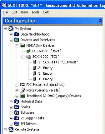
Once you are finished, your configuration in MAX should look like the screen-shot below.
Note: You should not configure the SCXI-112x modules in MAX because they are not intended to communicate directly with the DAQ device. You will still need to scale the data according to the gain settings on the SCXI-112x as described in the “Scaling Data” section below.
1. Open Measurement & Automation Explorer.
2. Expand Devices and Interfaces >> Traditional DAQ (Legacy) Devices by clicking the + symbol. You should see the E Series DAQ device name and number listed.
3. Insert a new SCXI chassis by right-clicking over Traditional DAQ (Legacy) Devices and selecting Add SCXI Chassis… from the menu and click Next. This causes a window to appear with a list of chassis types.
4. From this list, choose the SCXI chassis type that is cabled directly to the E Series DAQ device.
5. A window appears allowing you to choose the chassis ID and chassis address. Choose the lowest chassis ID available. The lowest chassis ID available is 1 if no other SCXI chassis are currently configured. For each subsequently cabled SCXI chassis, choose chassis ID values in ascending order from n. If you have no other SCXI chassis under Devices and Interfaces, this ID number should be 1, as shown in the drawing from the Overview section of this document.
6. Set the chassis address to the number that you set on the address switches on the particular SCXI chassis. Click Next.
7. Choose No when asked if you would like the software to automatically detect the modules in the chassis. Click Finish.
8. Now click the + to expand the newly added SCXI chassis and add the SCXI-1141 module in slot 1. To do this, right-click on the Module 1: Empty, click Insert, and select the SCXI-1141 from the list. Click Next and select the E Series DAQ device in the Connected To: field and leave the Operating Mode: at Multiplexed Mode. Configure the rest of the properties of the module to match any jumper settings on the board or to match the application if there are no jumpers.
9. Now, add the SCXI-112x modules in the appropriate slots in a similar manner. The SCXI-112x modules should be configured to be Connected To: None and Operating Mode: Parallel Mode. Configure the rest of the properties of the module to match any jumper settings on the board or to match the application if there are no jumpers.
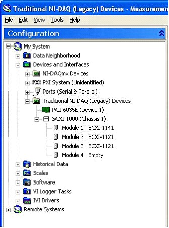
10. For example, with an SCXI-1141 in slot 1, an SCXI-1121 in slot 2, and an SCXI-1121 in slot 3, your final configuration should look like the screen-shot below.
Acquiring Data
Read data directly from the SCXI-1141. If the SCXI-1141 is in slot 1, then all software calls acquire data from module 1. Do not try to acquire data from the slots containing the SCXI-112x modules, as this returns an error. Refer to the DAQ Getting Started Guide for details on acquiring data off of the SCXI-1141.
Channel Mapping
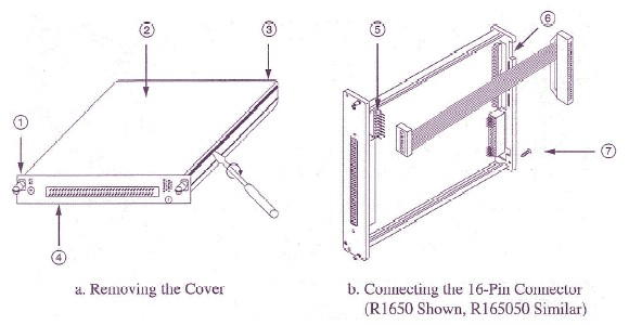
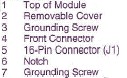
If you are using the R1650 cable, signals from channels 0 through 7 of the SCXI-1120 are read from channels 0 through 7 of the SCXI-1141 module, respectively. If you are using the R165050 cable, signals from channels 0 through 3 of the SCXI-1121 module in the slot to the immediate right (connected by the shorter half of the R165050 cable) of the SCXI-1141 module are read from channels 0 through 3 of the SCXI-1141 module, while signals from channels 0 through 3 of the SCXI-1121 module in the slot to the far right (connected by the longer half of the 165050 cable) of the SCXI-1141 module are read from channels 4 through 7 of the SCXI-1141 module.
Scaling Data
Data acquired from the cascaded SCXI-1141 and SCXI-112x module using standard NI-DAQ or LabVIEW functions are not properly scaled. Since data is acquired directly from the SCXI-1141 module, its data is scaled correctly for the SCXI-1141 gain, but not for the SCXI-112x gain. To determine the actual input signal voltage, divide the acquired voltage readings by the hardware gain setting of the SCXI-112x channel from which the signal was input. Use the following formula to scale the data:
V actual = V acquired / Gain 112x
Where V actual is the actual input signal voltage, V acquired is the voltage reading obtained using NI-DAQ or LabVIEW voltage scaling functions, and Gain 112x is the gain setting of the SCXI-112x input channel.
NI DAQmx
The shipping examples for your ADE are sufficient for acquiring data directly from the connected SCXI module. You will need to modify the program to scale the data properly based on the settings of the non-connected SCXI modules. Refer to the Scaling Data section of this tutorial for further details.
Traditional NI-DAQ (Legacy)
The Developer Zone has a number of SCXI module cascading example programs for Traditional DAQ with LabVIEW. Each includes a detailed description of hardware configuration and explanation of how to use it. LabVIEW also ships with a few examples programs for cascading SCXI modules. The following example program links are all traditional NI-DAQ examples.