From Friday, April 19th (11:00 PM CDT) through Saturday, April 20th (2:00 PM CDT), 2024, ni.com will undergo system upgrades that may result in temporary service interruption.
We appreciate your patience as we improve our online experience.
From Friday, April 19th (11:00 PM CDT) through Saturday, April 20th (2:00 PM CDT), 2024, ni.com will undergo system upgrades that may result in temporary service interruption.
We appreciate your patience as we improve our online experience.
This tutorial is part 2 of a three part series that discusses switching low-level voltage,current, and resistances. Each tutorial in this series, will provide you with insights on low-level switching for various different applications and measurement types. This tutorial introduces and discusses the techniques and challenges when switching low-current signals.
The other tutorials in this series are:
Signals in the 1 μA range or less are generally considered low-current and as in the case of low voltage signals, require special care when routed. Once again minimizing system error is essential because even a small offset current arising from the system can significantly raise percentage error and thus affect signal integrity. Some main obstacles to overcome when switching low-current signals are leakage currents arising from the switching system and cable connections, offset currents, and debounce time of the relay.
Leakage current is the total amount of error current flowing through a switching circuit to a location other than its output. Some of the main factors that contribute towards leakage current include:
a. Signal voltage level
b. Currents from parasitic elements in a circuit
c. Current radiated by components in close proximity to switching circuit (for example, a neighboring switch channel, high voltage sources, fluorescent lighting, and so on)
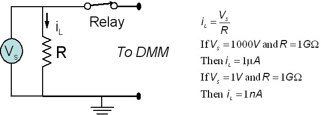
One of the many factors that contribute towards leakage current is the voltage level of the signal. A 1000V signal will bring about a much higher leakage current than a 1 V signal. This is because in most switching circuits, there is generally some resistance between the relay leads and ground. Factors that contribute to this resistance include the inherent resistance of the PCB in the switch module, component packaging, and dust particles that may have settled on the surface of the module PCB. Even though this resistance is usually very large (GΩ range) a small amount of current flows through it. The current that is lost while flowing through the resistor is a subset of leakage current. The amount of leakage current depends on the voltage level of the signal. For example let us consider the leakage current produced when routing two different signals through the circuit shown in Figure 2. The first signal has a voltage level of 1000 V while the second has a voltage level of 1 V. In the circuit shown below, VS is the voltage level of the signal, iL is the leakage current produced by VS and R, where R is the resistance between the relay and ground.
Figure 2. Dependence of Leakage Current on Voltage Level of Signal
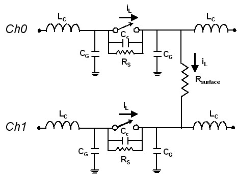
In addition to signal levels, hidden parasitic elements that form part of a switching circuit also contribute significantly to the net leakage current in a switching system. The circuit in Figure 3 highlights some of the many unwanted elements that may reside in a real world switching system. CG is the parasitic capacitance between the relay lead and ground. Every time this capacitor discharges, a leakage current flows through the circuit. RS is the leakage resistance across the contacts of a relay caused due to PCB resistance, conductance of air, pollution and several other factors. This resistance which is usually in the GΩ range provides a path for error current to flow through the switch even when it is open.
Another source for leakage current is the effect of sources outside the switching circuit. Factors such as pollution, dust, resistance of air, and PCB resistance, provide a path for current from sources such as fluorescent lighting, high voltage sources, and the a neighboring channel on a switch module to leak in to the switching circuit. Figure 3 displays how current leakage takes place from one channel to another in a switch module via resistor Rsurface. Factors that contribute to Rsurface are resistance of PCB in the switch module, resistance in air, and dust particles on the PCB surface.
Figure 3: Leakage Current Caused by Neighboring Switch Channel
There are ways to avoid leakage current. Since leakage current is caused by parasitic elements that exist in a circuit, it is important to make sure that the circuit measuring low-current signals is placed in a humidity and pollution controlled environment. Humid air is a better conductor of electricity and thus has a lower resistance value than dry air. Additionally, isolation between different components of a circuit can help increase the resistance between them and thus reduce leakage currents. Lastly, using shorter cable lengths can help reduce leakage currents by reducing net inductance and impedance in the circuit.
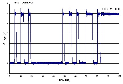
Armature and reed relay contacts “bounce” when they close. When closing, the contacts touch momentarily, making and breaking continuity, until finally remaining in the closed position. The concept of bouncing is analogous to that of a ball being dropped on the floor. When the ball is dropped it bounces for a few seconds before it gives up to the force of gravity and settles on the floor’s surface. Electromechanical relays are made up of contacts which meet each other to make or break the circuit. Since these contacts are made of metal, they have some mass. Furthermore, at least one of these contacts lies on a movable strip of metal which has springiness. Both these factors cause relay contacts to bounce as they make or break a connection. Figure 4 demonstrates relay bounce.
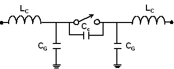
When bouncing occurs there is a transfer of charge which causes a current pulse in the circuit. This current pulse, while small, will add to the current of the signal being measured. The transfer of charge is due to a path being created in the circuit which allows the discharge of parasitic capacitances that exist in the circuit. Examples of such capacitances include those between two relay contacts and between the relay lead and ground. Every time the relay bounces between open and close states, these capacitances charge and discharge respectively.
Figure 4. Bouncing Occurs When a Relay Transitions Between Open and Close
From the above figure it can be seen that during the bounce time, the voltage applied to the circuit fluctuates. Once the relay contacts close completely, this voltage settles to a steady value. At this time, the erroneous transient currents generated due to the discharge or parasitic capacitances also reach a steady value and can be calibrated out of the system. Relay modules usually specify bounce time of relays. To minimize the effects of relay bouncing, it is advisable to wait longer than this specified number in order to make sure that measurements made are accurate.
Figure 5: Relay Circuit with Parasitic Capacitances
The cables carrying the current must be very well shielded to reduce noise currents due to electromagnetic interference and electric fields. NI recommends using cables with at least 90% shielding effectiveness. To protect the signal from environmental factors such as error currents due to humidity, the insulator should have low water absorption. Ideally, the cables should be in a humidity controlled, temperature controlled environment. Also, any movements in the cables can induce charge, so it is important to tie cables down so that they are stationary.
NI recommends selecting a cable with characteristics similar to the Belden 83317E, which is available at www.belden.com. Tape-wrapped polytetrafluoroethylene (PTFE) insulation guarantees low leakage. Copper conductors with silver plating perform very well for low-voltage measurements because of their low thermal characteristics.
To reduce measurement errors when routing low-current signals, always use shielded and twisted pair cables that are made of the same metal or material as the connector on the switch module. Such cables improve help limit transients in circuit thus reducing the net leakage current in the system.
View Part I and Part III of this tutorial series to learn more about low-level switching:
Customers interested in this topic were also interested in the following NI products: