PROFIBUS Overview
Overview
Contents
- PROFIBUS
- Master/Slave Concept
- Device and System Startup
- Cyclic I/O Data Exchange
- Device Diagnostic Reporting
- Programming Model
- Frequently Asked Questions
- Related Links
PROFIBUS
PROFIBUS extensions have always been developed to ensure backward compatibility. Figure 1 lists the extensions that have been standardized in the past few years.
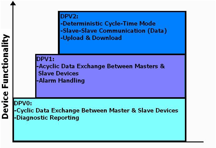
Figure 1. PROFIBUS DP Extensions
PROFIBUS DPV0 is the foundation for PROFIBUS and was the first version after FMS (Field Message Specification). DPV0 came from optimizations to FMS, the original PROFIBUS protocol, to support fast I/O data exchange.
PROFIBUS DPV1 added extensions that allowed run-time reading/writing of parameters for more sophisticated devices such as intelligent drives, for example, and PROFIBUS PA field instruments, such as valve positioners, pressure transmitters, and so on.
PROFIBUS DPV2 primarily added extensions, so that you can perform motion control applications directly across PROFIBUS rather than requiring a secondary motion control bus.
Master/Slave Concept
PROFIBUS DP (Decentralized Peripherals) is a network that is made up of two types of devices connected to the bus: master devices and slave devices. It is a bidirectional network, meaning that one device, a master, sends a request to a slave, and the slave responds to that request. Thus, bus contention is not a problem because only one master can control the bus at any time, and a slave device must respond immediately to a request from a master.
Because a request from a master to a slave device is heard by all devices attached to the bus, some mechanism must exist for a slave device to recognize that a message is designated for it and then respond to the sender. Hence, each device on a PROFIBUS network must have an assigned address. For specifying the address, most devices have either rotary switches (decimal or hexadecimal) or DIP switches. A few devices require that their addresses be set across the bus using a configuration tool.
The PROFIBUS protocol supports addresses from 0 to 127. However, addresses 126 and 127 have special uses and may not be assigned to operational devices. Address 0 has become something of a default address that vendors assign to network configuration and/or programming tools attached to the bus.
Thus, the addresses you can use for operational devices are 1 to 125.
Device and System Startup
You specify which slave devices the master should find on the bus as well as which information should be transferred from the master to each slave during this startup phase. All of the information that the master must know to start up the bus comes from a configuration database file that is generated by a PROFIBUS configuration tool. Each vendor of PROFIBUS master devices offers a configuration tool for generating the database file for their masters. However, once you have learned how to apply any of these tools, it is generally quite easy to transfer this knowledge to another tool because all PROFIBUS configuration tools must share certain common functionality. A configuration tool for cyclic I/O operation must be able to do the following:
- Process GSD (device description) files and maintain a hardware catalog of devices to be configured on the bus
- Allow the PROFIBUS device address to be specified
- Allow the specification of the input and output data to be transferred between master and slave
- Allow certain startup parameters to be selected to activate specific operating modes or features of the device
- Allow selection of the system baud rate
- Generate the database file so it can be used by the master
At the same time a vendor develops a slave device, it must develop a device description (GSD) file. This file completely describes the PROFIBUS functionality of the device, such as baud rates supported, possible input/output data configurations, startup parameter choices, and so on.
You can typically download these GSD files via the Internet either from www.profibus.com or from an individual vendor’s Web site. Once a user "installs" the GSD file for a device into the PROFIBUS configuration tool, it appears in the tool's hardware catalog, so it can be configured for bus operation.
The installation process varies for different configuration tools, but it is extremely simple. Once you have installed all of the appropriate GSD files in the configuration tool, you can define a bus configuration.
First pick the appropriate master from the master device list in the hardware catalog and assign a PROFIBUS address. You repeat the following steps until the entire bus configuration has been described: select a slave device, assign the PROFIBUS address, specify the I/O to be exchanged, and select the appropriate parameters for the desired operation of the device. You then save this bus configuration and generate the configuration database. You can now load this configuration database into the master device.
After download, the master has the information necessary to start up all the devices in its configuration. This information is stored in retentive memory. The master must now determine if the devices at the assigned addresses contained within the configuration database are physically on the bus and initialize them for "operational" or "data exchange" mode. To get the devices into this mode, a PROFIBUS master undergoes a well-defined sequence of interactions with each of the slave devices in its bus configuration. For instance, if the master device experiences a power loss, when it powers back up, it uses the configuration database in retentive memory to go through the startup sequence with each device in its configuration to get all devices back into operational mode. If a slave device fails and must be replaced, the master recognizes that a replacement device of the same type and with the same PROFIBUS address has been attached to the bus. When it does, it goes through this same startup sequence and automatically brings the device into operational mode.
Cyclic I/O Data Exchange
After the bus system has been powered and initialized, the normal interaction between a master and each of its assigned slaves is to exchange I/O data. The master, a PXI PROFIBUS interface, for example, sends output data to a slave device in its configuration. The addressed slave immediately responds with its input data. This cyclic (repeated) I/O data exchange takes place asynchronously to the control logic scan and is repeated as quickly as possible. Data exchange takes place every cycle for every slave in a master's configuration. At the most commonly used baud rate of 1,500kbits/s, data exchange cycles are normally repeated many times during a single control logic scan.
Although 85 percent or more of PROFIBUS installations are single-master systems, multimaster systems work quite well, too. In such a system, each master is given control of the bus for a short time, and, during this time, it exchanges I/O data with each of its assigned slaves. It then passes control to the next master on the bus, via a short message called a "token," and that master exchanges I/O data with each of its slaves. Only the master holding the token is allowed to initiate communication to its slaves. When the last master in the "logical token ring" has gone through its data exchange cycle, it passes control back to the first master, and the overall operation starts again.
Device Diagnostic Reporting
The PROFIBUS protocol offers extensive diagnostic capabilities that device vendors can design into their products. PROFIBUS provides the capability to diagnose an operations problem all the way down to, for example, an overvoltage on an analog input or a broken wire on an output.
During a data exchange cycle, a PROFIBUS slave device can indicate to the master that it has detected a diagnostic condition. In the next data exchange cycle, the master fetches the diagnostic information from the slave. A device can report diagnostic information in four different formats: standard diagnostics, device-related diagnostics, module-related diagnostics, and channel-related diagnostics.
Any PROFIBUS master must save any diagnostic data from a slave for your control program to access it. The standard diagnostics (six bytes) that every slave device is required to report contain information that is generally related to startup problems. For example, if the I/O configuration that was set up in the configuration tool does not match what the slave expects, it reports a "configuration fault." If you have configured a slave device in your configuration file, but the slave actually found on the bus at that address is different, the device reports a "parameterization fault." The six standard diagnostic bytes are used to report faults that are common across all slave devices.
A vendor can use the device-related diagnostics format to report information that may be specific to the particular device or application area and that cannot be reported using the standard module-related or channel-related diagnostic formats. The format of this type of diagnostic information is defined by the vendor, and its detailed structure is not covered in the PROFIBUS standard. Therefore, you must check the device's documentation to determine the exact format. Module-related diagnostics are used to report diagnostics for a modular slave, which is a slave that consists of an "intelligent" head module plus plug-in modules. This format gives the head module the capability to report that a particular plug-in module has a diagnostic. It does not communicate what the diagnostic is – just that a particular module has a problem. The format for module-related diagnostic information is defined in the PROFIBUS standard. This means that once a logic block is constructed to decode this type of diagnostic information, the decode logic works for any device from any vendor that reports module-related diagnostics.
The last type of diagnostic block is used to report channel-related diagnostics. A device can use this format to report that an individual channel of a specific module has a problem, for example, short circuit, wire break, overvoltage, and so on. This makes it very easy to diagnose the problem right down to the wire level. The format for this type of diagnostic information is also defined in the PROFIBUS standard. The exact formats of these different diagnostic information blocks are presented in Appendix A.
Programming Model
The PROFIBUS software package includes standard VIs to initialize the PROFIBUS network and to access the DP Slave I/O and diagnostic data. Refer to the LabVIEW Examples and Context Help for further details.
Note: All PROFIBUS hardware sold by NI uses the same KUNBUS Configurator software. The PXI and PCI interfaces are programmed with the NI-PROFIBUS driver, and the CompactRIO PROFIBUS module is programmed with the NI-PROFIBUS for CompactRIO driver.
PROFIBUS DP Master API
Basic API for NI-PROFIBUS
- The Init, Abort VI initializes and closes the DP Master interface handle and delivers the Slave Poll List.
- The Master Process Data VI makes the data exchange with a single or multiple slaves, as shown in Figure 2.
- The NI-PROFIBUS for CompactRIO API is a LabVIEW FPGA VI-based API that follows a similar communication flow using Initialize, Read/Write data from the FPGA memory and module, and Abort functions.
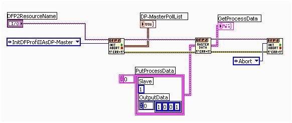
Figure 2. DP Master API for PXI and PCI
Express VI
- For easy access to a single slave device, a PROFIBUS Master Express VI is available for the PXI and PCI interfaces. When the Express VI is placed onto the block diagram, a configuration dialog opens to enter the DF PROFI II board and the PROFIBUS address of the slave.
- The Monitor/Modify tab shows the input and output data as well as the communication status of the slave device. You can modify the output data by clicking directly in the value field and entering new data. You must enter the data points in the same format as displayed or they are ignored.
- The Diagnostic tab shows the diagnostic data transmitted by the slave device. The data is displayed in clear text for the standard PROFIBUS diagnostic data and in hexadecimal format for the extended diagnostic data.
PROFIBUS DP Slave API
Basic API for NI-PROFIBUS
- The Init, Abort VI initializes and closes the DP Slave interface handle and configures the Slave Memory.
- The Slave I/O Data VI makes the data exchange with a single Master as shown in Figure 3.
- The NI-PROFIBUS for CompactRIO API is a LabVIEW FPGA VI-based API that follows a similar communication flow using Initialize, Read/Write data from the FPGA memory and module, and Abort functions.
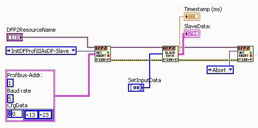
Figure 3. DP Slave API for PXI and PCI
Express VI
- For easy access, a PROFIBUS Slave Express VI is available for the PXI and PCI interfaces. When dropping the Express VI to the block diagram, a dialog opens to configure the slave device. Select the DF PROFI II board, the PROFIBUS address of the slave, and the baud rate.
- The Configuration tab shows the supported slave modules. The selected module must correspond with the PROFIBUS master configuration.
- The Monitor/Modify tab shows the input and output data as well as the communication status of the slave device. You can modify the output data by clicking directly in the value field and entering new data. You must enter the data points in the same format as displayed or they are ignored.
Frequently Asked Questions
1. Which PROFIBUS DP functionality is supported by the KUNBUS DF PROFI II board?
- DPV0 Master Class 1/ 2
- DPV0 Slave
- DPV1 Master Class 2
- Process data image with timestamp
2. What is the PIN assignment of the DF PROFI II Sub D9 plug?
| Pin | Signal | Function |
| 1 | --- | Shielding |
| 3 | RxD/TxD-P | Data+ (input/output) |
| 5 | 0V | Bus termination supply (input) |
| 6 | 5V | Bus termination supply (output) |
| 8 | RxD/TxD-N | Data- (input/output) |
3. What is the DF PROFI II LED configuration?
PXI and PCI PROFIBUS Interfaces
| LED | State | Function |
| Green | OFF | Firmware not loaded |
| ON | Firmware successfully loaded | |
| Yellow | OFF | PROFIBUS stopped |
| ON | PROFIBUS started | |
| Red | OFF | NO Failure on PROFIBUS |
| ON | Failure on PROFIBUS |
CompactRIO PROFIBUS Module
| PWR (Power Indication) | OFF | No power supply connected |
| ON | Power supply connected | |
| SPI (Activity) | OFF | SPI bus not active |
| ON | SPI bus active | |
| RUN (PROFIBUS Activity) | OFF | Master Mode: Scanning not activated Slave Mode: DP Slave not active |
| ON | Master Mode: Scanning activated Slave Mode: DP Slave initialized | |
| BF (PROFIBUS Bus Fail) | OFF | Master Mode: PROFIBUS OK Slave Mode: Data exchange OK |
| ON | Master Mode: PROFIBUS Bus Fail Slave Mode: No exchange with DP Master (see manual for possible reasons) |
4. Why is termination important?
Termination prevents reflections that can disturb the data communication. The higher the baud rate and the longer the cable, the more important termination becomes. Termination should be activated/placed at both ends of every bus segment. With PROFIBUS DP, the termination is powered to provide an idle level when nobody is sending data.
You may be aware that termination has to be powered and placed at both ends of the cable, but you may not know that you have to place the termination again when you are using repeaters, OLMs (Optical Link Modules) or ProfiHubs. Every segment has to be terminated. This often slips in when you are using a lot of fiber-optic cable and there is only a short length of copper cable in the cabinets. But even this short cable has to be terminated at both ends.
5. What are some basic tips for installing a PROFIBUS DP?
- Always use PROFIBUS cable and connectors.
- Do not exceed 32 devices per segment (including repeaters, OLMs, and couplers).
- Make sure the segment length is in contrast with the baud rate.
- Make sure every segment has powered termination on both ends.
- Avoid spur lines.
- Avoid swapping the wires (A=green, B=red).
- Mark how long the cables really are and update the drawings.
- After installation you should test your work:
Are the addresses correctly set?
No short circuit or break in the cable?
Can you communicate with the devices?
6. What is the minimum distance between two devices on PROFIBUS DP?
When the transmission speed is 1.5 Mbits/s or higher, it is highly recommended to have at least 1 m of cable between 2 devices. The cable compensates for the input capacitance of both devices to preserve the common impedance. When the devices are very close together, there is a large chance that reflections in the data communication (small short circuits) can be caused by the input capacitance. The effect is much less common at transmission speeds lower than 1.5 Mbits/s.
7. How many DP slaves can I configure in a network?
Most people say 126, but this is NOT true. The total number of DP slaves that you can incorporate in a data exchange is 124 because the master uses an address and there are reserved addresses, 0 and 126 (these are blocked by the configuration tool).
Be careful:
- Address 2 could also be blocked for slaves.
- The master itself can have a limit.
8. How can I control the outputs of one slave with two masters (PLCs)?
This is not possible. Only one master has the right to control the outputs of each specific slave (safety feature). The second master can only READ the inputs/outputs.