DAQ_Digital Edge Count Measurement Library
- Aktualisiert2025-04-25
- 5 Minute(n) Lesezeit
DAQ_Digital Edge Count Measurement Library VIs initialize, configure, measure, and close user-configurable PFI lines using selected counters for digital events or edge counting. This library is applicable for digital I/O channels and modules that support timing input signals with PFI channels or other connections.
- Use the DAQ_DECM Initialize VI to initialize hardware and create DAQmx
Tasks for digital edge count measurement.
The Count Digital Events library requires two DAQmx tasks: a counter task for edge counting and a timer task used for hardware-timed wait types to precisely control measurement time.
- For the timer task, provide a counter resource to generate the measurement window for a hardware-timed wait type. No external physical connections are required. The counter task uses the generated pulse internally. For software-timed wait types, leave the Counter – Timer input empty.
- For the counter task, provide a counter resource and input terminal to listen for digital events or edges. Refer to the NI-DAQmx Device Terminals Help table. To access the table in NI MAX, select your device and right-click Device Pinout. Use the table to view the default PFI terminals of each counter for your device.
- If necessary, configure PFI lines.Note For the TestScale TS-15050 module only, P0.DIO<0:7> channels map to PFI<0:7> terminals. Refer to the TS-15050 Specifications for more information.
- Pass the digital edge count measurement DAQmx Task to the DAQ_DECM Configure and
Measure VI. Refer to the following sections for more information
about configuration settings.
-
- Execution Settings—By default, the Configure and Measure VI also executes the
measurement. If you are using a trigger for your
measurement, choose the Configure Only or Measure Only
execution option to avoid automatic execution.Note For software-timed wait types, a Measure Only operation returns the current counter value immediately. It does not wait for the specified duration.
- Counter Settings—These setting specify the active edge to count, the count duration, and the wait type (either software-timed or hardware-timed).
- Timer - Trigger Settings—These settings control the start of the hardware-timed counting with a digital start trigger.
- Output Data—The VI returns the number of edge counts at the end of measurement duration.
-
- Close the digital edge count measurement task using DAQ_DECM Close VI.
Execution Option Settings
Hardware Timed Digital Edge Counting
With hardware-timed digital edge counting, a timer task precisely controls the count measurement time by generating a single pulse of the specified duration that starts or stops the counting process. This is suitable for high-frequency inputs that require precise a measurement time for edge counting.
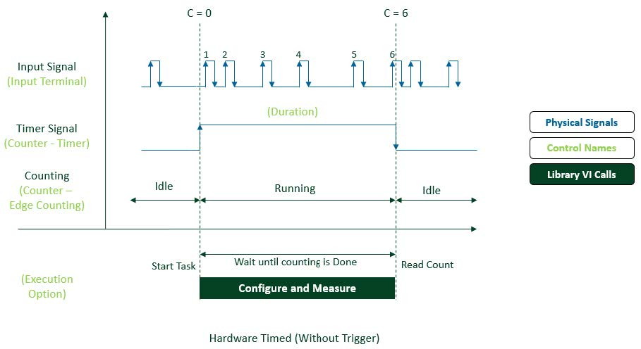
The following timing diagram illustrates hardware-timed digital edge counting. In this case, the timer task controls the measurement time by generating a pulse signal of the specified duration.
Calling the Configure and Measure VI starts the edge counting, waits for the specified measurement duration (counting happens until the timer pulse signal goes low) and finally measures the counter value.
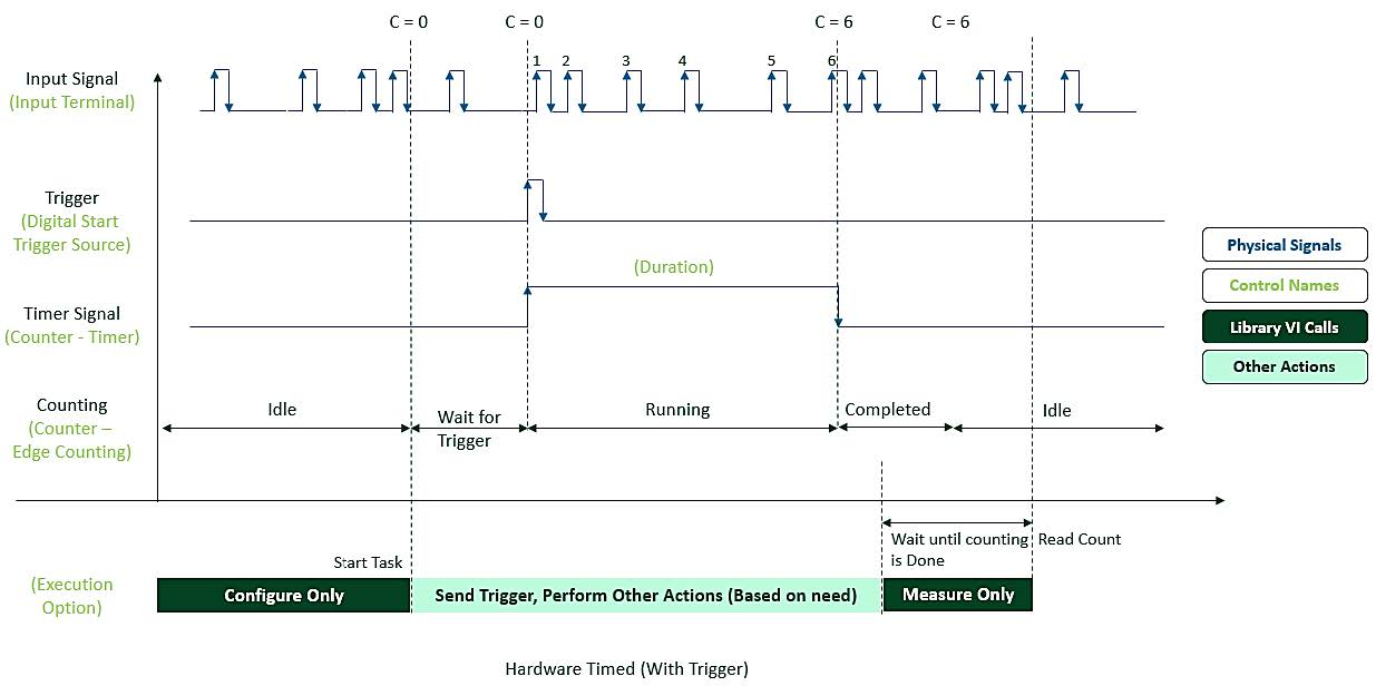
The following timing diagram illustrates hardware-timed digital edge counting with a trigger. In this case, the digital start trigger source controls the timer start.
The Configure Only call configures the trigger, starts the task and wait for the trigger to start the timer and edge counting. At that point, you can send the trigger and perform additional actions. The Measure Only call waits for the specified measurement duration and then reads the counter value.
Software Timed Digital Edge Counting
With software-timed digital edge counting, counting starts as soon as the task starts. After an internal or external software-timed wait, the edges are counted.
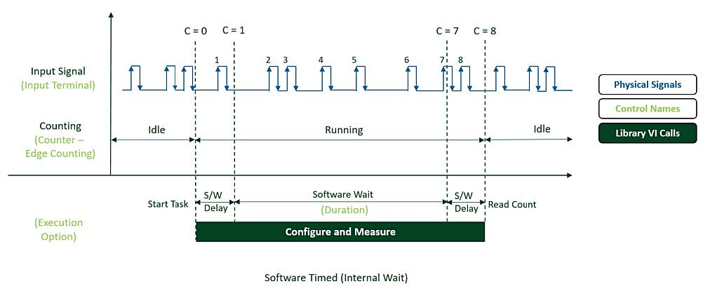
The following timing diagram illustrates software-timed digital edge counting that uses the library VI to add the wait internally.
The Configure and Measure call starts the edge counting, waits for the specified measurement duration, and finally measures the counter value. With this method, software delays can affect the counting process to produce measurements that are less precise.
This method is suitable for low-frequency inputs that do not require a precise measurement time for edge counting.
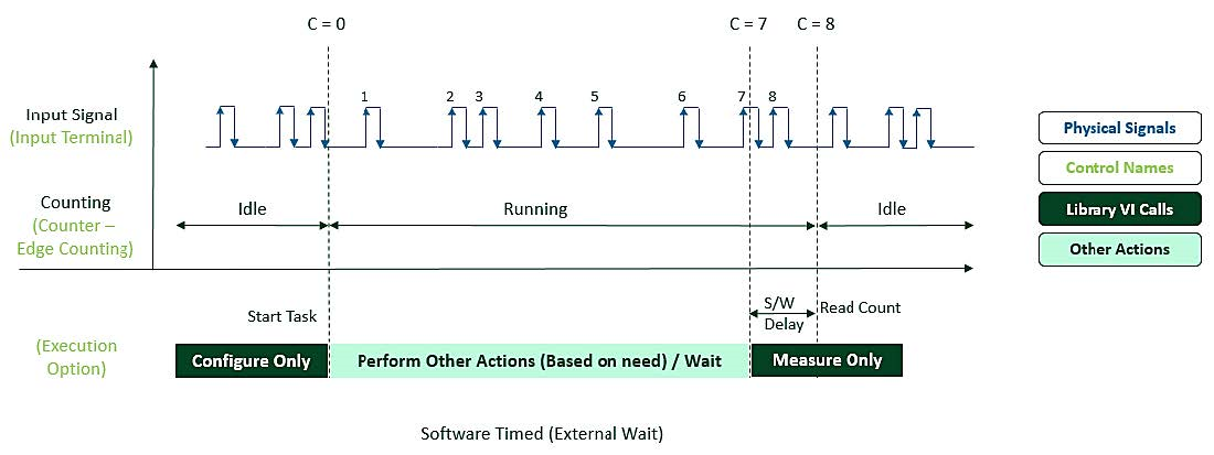
The following timing diagram illustrates software-timed digital edge counting that uses an external, user-defined software wait. The library VI does not wait during the measurement.
The Configure Only call starts the edge counting. During the measurement duration you can wait in the test layer or perform other actions before using a Measure Only call to read and return the counter value.
This method is suitable for low-frequency inputs with long measurement times that during which you can perform other operations. You can also wait and measure in a separate thread.