Functional Prototyping Series: Algorithm Engineering
Overview
The Functional Prototyping Series is a collection of articles that walk you through the prototyping processs. Read on for key concepts, benefits of prototyping, product choice discussion, and additional technical resources.
Contents
- Algorithm Engineering
- Algorithm Engineering Challenges
- The Advantages of Graphical System Design for Algorithm Engineering
- Next Steps
- Related Resources
- Next Steps
Algorithm Engineering
Algorithm engineering is a term coined for applied algorithm design. It refers to the process of transforming a pencil-and-paper algorithm into a robust, well-tested, and easy-to-use implementation. Implementing an algorithm to provide desired functionality in a prototype can be the most challenging part of the whole product development life cycle, but it also has the potential to be the most rewarding. By applying real-world I/O, you can see the functionality of your algorithm come to life before your eyes.
This article examines some of the pitfalls that a developer may experience while designing algorithms as well as the advantages to using graphical system design to overcome these challenges.
Algorithm Engineering Challenges
Implementing algorithms in a functional prototype can be difficult for a variety of reasons:
Programming limitations.
Often control systems or processors that are chosen for their I/O capabilities, such as field-programmable gate arrays (FPGAs), involve programming limitations for a developer. Programming for different platforms usually requires programming knowledge that few system-level designers are adequately proficient in.
Basic algorithm implementation.
Implementing low-level algorithms for basic functionally takes time. Speed is paramount in prototyping, and designers often cannot afford to get bogged down in implementing a well-known algorithm from scratch due to the lack of existing code.
Reworking algorithms for multiple platforms.
As the functional prototype evolves, many times algorithms have to be revisited to port them to a different type of system. Code is rarely functional between different run-time environments, and that makes scaling an application from prototyping to deployment difficult.
Test and verification.
It is difficult to know for sure whether a system can meet functional requirements until late in the game, and it is costly to start over. For example, the processor may not be able to perform the required number of parallel tasks fast enough. It may not be able to achieve adequate cycle time. It also may not be able to handle the processor-intensive analysis in real time.
The Advantages of Graphical System Design for Algorithm Engineering
Graphical system design addresses and mitigates many of the potential pitfalls involved in engineering algorithms for a functional prototype. Graphical system design is an approach to solving design challenges that blends intuitive graphical programming and flexible commercial off-the-shelf (COTS) hardware. With this approach, you can use a single environment across all stages of design. Now take a more in-depth look at how this approach specifically addresses the challenges raised above.
Multiple Models of Computation
One of the virtues of graphical system design is that it gives programmers the ability to create their algorithms regardless of the model of computation (MoC) they are implemented with. As code complexity for algorithms continues to grow, programmers have to use different MoCs to expand their coding capabilities. The following are just a few models of computation that you can use with graphical system design:
Data flow
Data flow is the MoC most often associated with NI LabVIEW software. With data flow, operations require the developer to insert data in all the inputs before it executes. Data flow is an intuitive coding structure that makes implementing applications such as parallel processes easy.
Textual math
Textual math is another tool for creating complex functions easily. Text-based math is a human-readable implementation of often complex algorithms that are easier to write in a script description form. Examples of textual math are the formula node and MATLAB Script node. With LabVIEW, you can choose the most effective syntax for algorithm development, whether you are developing algorithms, exploring signal processing concepts, or analyzing results.
C code
Sometimes the algorithm you use was originally created in C or C++. In this case, you no longer have to discard the previous work. You can instead use the Inline C Node or the Call Library Function Node to directly call your previous code within LabVIEW. Use the Inline C Node for preexisting C code or implementing a small numeric or array algorithms and use the Call Library Function Node to access C code in DLLs or shared libraries.
Learn more about using Python, MathWorks®MATLAB® Software, and C/C++ with LabVIEW
Open Software Architecture
Over the years, the LabVIEW platform has seen wide-scale adoption in numerous design disciplines, resulting in a need to incorporate data with different design and simulation tools. LabVIEW accomplishes this intercompatibility with numerous integration tools, libraries, and file formats. LabVIEW also offers a large array of standard integration with other software tools and measurement resources including the following:
- DLLs, shared libraries
- ActiveX, COM, and .NET (Microsoft)
- DDE, TCP/IP, UDP, Ethernet, Bluetooth
- CAN, DeviceNet, Modbus, OPC
- USB, IEEE 1394, RS232/485, GPIB
- Databases (ADO, SQL, and so on)
Using these tools, integration with data from almost every kind of measurement and control device is possible. By combining LabVIEW with general-purpose standards for hardware communication, developers can ensure compatibility and scalability for many years in the future.
The LabVIEW Approach
The hundreds of functions in LabVIEW that cover a wide variety of traditional algorithms in math, signal processing, probability, and control are essential building blocks for any custom algorithm. These functions alleviate the burden of writing low-level code and give engineers the time to focus on a solution instead of implementation.
Because using LabVIEW makes acquiring real-world data so easy, users find it valuable to test their algorithms with actual data as an iterative approach to tuning them. With this interactive test approach, you can experiment with different functions to see if they provide the required expected result. For example, when processing a signal with a filter, you can select from a wide variety of solutions, acquire the actual signal that you need, and look at the results in either a graph or file. If the results are not suitable for the application, then you can select another filter. Often it is easier to acquire the actual signal to apply to an algorithm then to take the time to simulate it on software.
COTS Hardware
Commercial off-the-shelf hardware not only offers a cheap way to quickly begin prototyping but also, with graphical system design, helps you implement native algorithms on a large number of different targets with integrated I/O. Use real-time processors such as those found on the NI CompactRIO and PXI platforms to integrate I/O with deterministic control for additional reliability. This is essential in cases such as hardware-in-the-loop applications, where you need to tightly integrate hardware and software to dynamically simulate the environment that the control algorithms are trying to control.
Besides using just real-time processors with FPGAs, you can incorporate LabVIEW into your application to transport code from one type of COTS hardware to another. For instance, you can transport code that analyzes a signal on a desktop for real-world I/O and use it in form factors such as PXI modules or embedded processors without having to significantly rewrite it. In fact, designing and verifying a prototype first on a desktop and then transferring it to a 32-bit processor for deployment in an embedded system can save significant development time and costly rework due to missed design constraints.
Tools for Simulation and Control Design
Because LabVIEW is an open platform, you can map your measurement data against simulated results. You can even interchange simulated and physical data for behavioral modeling. In addition, you can drive physical tests with simulated stimuli to provide a robust testing environment.
Use simulation with LabVIEW to verify and predict performance for design criteria. You can import designs into separate simulation tools for early design evaluation. The next step involves automated layout or model formation and tooling to automate the build process. Saving system state information and output signals if applicable helps you debug applications as well as establish specifications for the application performance.
Use control block diagrams such as those found in the LabVIEW Control Design and Simulation Module to design a linear, nonlinear, discrete, or continuous control system. With this abstracted programming style, you can program with traditional control concepts such as transfer function blocks, integrators, differentiators, and feedback loops. Using this high-level block diagram, you can develop solutions from the conceptual level, where you can pull from your previous experience and knowledge about a system.
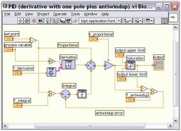
Figure 1. PID Control with Control Design and Simulation
Next Steps
Engineering the algorithms that implement the functionality of your prototype can be a challenging process. Graphical system design is an approach that takes advantage of tight integration between intuitive graphical software and COTS hardware to help you overcome the challenges associated with algorithm engineering to get your prototype up and running fast at a lower cost.
To learn more about the technical aspects of transitioning from a paper design to a software design, see the related resources below.