Introduction to the LIN Bus Protocol
Overview
The Local Interconnect Network (LIN) Protocol is a low-cost embedded serial networking standard for connecting intelligent devices and is most popular in the automotive industry, where it enables communication between vehicle components.
Contents
- Overview of LIN
- LIN Frame Format
- LIN Bus Timing
- LIN Topology and Behavior
- LIN Error Detection and Confinement
- LIN Sleep and Wakeup
- Advanced Frame Types
- Recommended PC LIN Interfaces
- Additional LIN Information
Overview of LIN
The Local Interconnect Network (LIN) bus was developed to create a standard for low-cost, low-end multiplexed communication in automotive networks. Though the Controller Area Network (CAN) bus addresses the need for high-bandwidth, advanced error-handling networks, the hardware and software costs of CAN implementation have become prohibitive for lower performance devices such as power window and seat controllers. LIN provides cost-efficient communication in applications where the bandwidth and versatility of CAN are not required. You can implement LIN relatively inexpensively using the standard serial universal asynchronous receiver/transmitter (UART) embedded into most modern low-cost 8-bit microcontrollers.
Modern automotive networks use a combination of LIN for low-cost applications primarily in body electronics, CAN for mainstream powertrain and body communications, and the emerging FlexRay bus for high-speed synchronized data communications in advanced systems such as active suspension.
The LIN bus uses a master/slave approach that comprises a LIN master and one or more LIN slaves.
Figure 1. LIN Message Frame
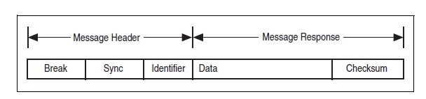
The message header consists of a break used to identify the start of the frame and the sync field used by the slave node for clock synchronization. The identifier (ID) consists of a 6-bit message ID and a 2-bit parity field. The ID denotes a specific message address but not the destination. Upon reception and interpretation of the ID, one slave begins the message response, which consists of one to eight bytes of data and an 8-bit checksum.
The master controls the sequencing of message frames, which is fixed in a schedule. You can change the schedule as needed.
There are several versions of the LIN standard. Version 1.3 finalized the byte-layer communication. Versions 2.0 and 2.1 added more messaging specifications and services but are compatible at the byte level with LIN 1.3.
| Feature | Supported by NI USB LIN |
| LIN 1.3 | Yes |
| LIN 2.0 | Yes1 |
Enhanced checksum | Yes |
Off-the-shelf slave node concept | Yes1 |
NCF format | Yes1 |
Diagnostics and slave node configuration | Yes1 |
Byte arrays | Yes |
| LIN 2.1 | Yes1 |
New slave node configuration services | Yes1 |
Slave diagnostics class I-III | Yes1 |
Functional addressing | Yes1 |
Resolution table | Yes1 |
1This feature is not natively supported by the API; however, you can implement the functionality.
Table 1. Comparison of LIN Versions 1.3, 2.0, and 2.1
LIN Frame Format
The LIN bus is a polled bus with a single master device and one or more slave devices. The master device contains both a master task and a slave task. Each slave device contains only a slave task. Communication over the LIN bus is controlled entirely by the master task in the master device. The basic unit of transfer on the LIN bus is the frame, which is divided into a header and a response. The header is always transmitted by the master node and consists of three distinct fields: the break, synchronization (sync), and identifier (ID). The response, which is transmitted by a slave task and can reside in either the master node or a slave node, consists of a data payload and a checksum.
Normally, the master task polls each slave task in a loop by transmitting a header, which consists of a break-sync-ID sequence. Prior to starting the LIN, each slave task is configured to either publish data to the bus or subscribe to data in response to each received header ID. Upon receiving the header, each slave task verifies ID parity and then checks the ID to determine whether it needs to publish or subscribe. If the slave task needs to publish a response, it transmits one to eight data bytes to the bus followed by a checksum byte. If the slave task needs to subscribe, it reads the data payload and checksum byte from the bus and takes appropriate internal action.
For standard slave-to-master communication, the master broadcasts the identifier to the network, and only one slave responds with a data payload.
Master-to-slave communication is accomplished by a separate slave task in the master node. This task self-receives all data published to the bus and responds as if it were an independent slave node. To transmit data bytes, the master must first update its internal slave task’s response with the data values it wants to transmit. The master then publishes the appropriate frame header, and the internal slave task transmits its data payload to the bus.
Figure 2. LIN Message Frame
1. Break
Every LIN frame begins with the break, which comprises 13 dominant bits (nominal) followed by a break delimiter of one bit (nominal) recessive. This serves as a start-of-frame notice to all nodes on the bus.
2. Sync
The sync field is the second field transmitted by the master task in the header. Sync is defined as the character x55. The sync field allows slave devices that perform automatic baud rate detection to measure the period of the baud rate and adjust their internal baud rates to synchronize with the bus.
3. ID
The ID field is the final field transmitted by the master task in the header. This field provides identification for each message on the network and ultimately determines which nodes in the network receive or respond to each transmission. All slave tasks continually listen for ID fields, verify their parities, and determine if they are publishers or subscribers for this particular identifier. The LIN bus provides a total of 64 IDs. IDs 0 to 59 are used for signal-carrying (data) frames, 60 and 61 are used to carry diagnostic data, 62 is reserved for user-defined extensions, and 63 is reserved for future protocol enhancements. The ID is transmitted over the bus as one protected ID byte, with the lower six bits containing the raw ID and the upper two bits containing the parity.
| Protected ID(7:6) | Protected ID(5:0) | |
| P(1) | P(0) | ID(5:0) |
| ID(1) ^ ID(3) ^ ID(4) ^ ID(5) | ID(0) ^ ID(1) ^ ID(2) ^ ID(4) | 0–63 |
Table 2. Parity Calculation Method
4. Data Bytes
The data bytes field is transmitted by the slave task in the response. This field contains from one to eight bytes of payload data bytes.
5. Checksum
The checksum field is transmitted by the slave task in the response. The LIN bus defines the use of one of two checksum algorithms to calculate the value in the eight-bit checksum field. Classic checksum is calculated by summing the data bytes alone, and enhanced checksum is calculated by summing the data bytes and the protected ID.
The LIN 2.0 specification defines the checksum calculation process as the summing of all values and subtraction of 255 every time the sum is greater than or equal to 256 (unlike modulo-255 or modulo-256). Per the LIN 2.0 specification, classic checksum is for use with LIN 1.3 slave nodes and enhanced checksum is for use with LIN 2.0 slave nodes. It further specifies that IDs 60 through 63 shall always use classic checksum. The NI LIN interface provides an attribute to set the checksum type to classic or enhanced. The default setting is classic. Per the LIN 2.0 specification, IDs 60 through 63 always use classic checksum, regardless of the setting of the checksum attribute.
Figure 3 illustrates how a master task header and a slave task response combine to create a LIN full frame.
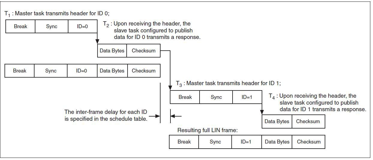
Figure 3. Creation of LIN Frames
LIN Bus Timing
Because the LIN bus is a polled bus, the processing of each frame is allocated a nominal time slot as follows:
THeader_Nominal = 34 * TBit
TResponse_Nominal = 10 * (NData + 1) * TBit
TFrame_Nominal = THeader_Nominal + TResponse_Nominal
Processing of each frame is allocated a maximum time slot as follows:
THeader_Maximum = 14 * THeader_Nominal
TResponse_Maximum = 1.4 * TResponse_Nominal
TFrame_Maximum = THeader_Maximum + TResponse_Maximum
LIN Topology and Behavior
The LIN bus connects a single master device (node) and one or more slave devices (nodes) together in a LIN cluster. The behavior of each node is described by its own node capability file. The node capability files are inputs to a system-defining tool, which generates a LIN description file (LDF) that describes the behavior of the entire cluster. The LDF is parsed by a system generator to automatically generate the specified behavior in the desired nodes. At this point, the master node master task starts transmitting headers on the bus, and all the slave tasks in the cluster (including the master node’s own slave task) respond, as specified in the LDF.
In general terms, the LDF is used to configure and create the scheduling behavior of the LIN cluster. For example, it defines the baud rate, the ordering and time delays for the master task’s transmission of headers, and the behavior of each slave task in response. NI LIN hardware and the NI-CAN Frame API for LIN do not natively provide full support for LDFs, meaning that you cannot download scheduling behavior into the hardware. However, the low-level support of accessing the bus (writing headers and publishing or subscribing to responses) is provided such that the user may create this scheduling behavior at the application level. As mentioned in the description for the NI LIN response entry frame type, NI LIN hardware features a response queue for storing slave task responses. The response queue holds 64 responses, one for each of the maximum number of 64 IDs specified for LIN. This ensures that the LIN interface slave task can respond to headers within the response time defined by the LIN specification.
The NI-CAN Frame API for LIN offers a robust means of complete, low-level interaction with the LIN bus. This provides the end user with the basic functionality from which to develop complex applications involving the analysis and prototyping of LIN networks. The NI-CAN Frame API for LIN does not natively support LIN diagnostics or configuration, LDFs, or schedule tables. However, you may implement these tasks in applications that use the NI-CAN Frame API for LIN.
LIN Error Detection and Confinement
The LIN 2.0 specification states that error detection should be handled by the slave tasks and that error monitoring by the master task is not required. The LIN 2.0 specification does not require the handling of multiple errors within one LIN frame or the use of error counters. Upon encountering the first error in a frame, the slave task aborts the processing of the frame until the detection of the next break-sync sequence (in the next header transmitted by the master). If the log bus errors attribute is set to true, a bus error frame is logged into the read queue. If the log bus errors attribute is set to false, an error is returned by ncWriteNet or ncWriteNetMult.
LIN also provides for error reporting to the network. The LIN 2.0 specification defines a Response_Error status bit, which the slave is required to report to the master in one of its transmitted frames. This bit is set whenever a frame received or transmitted by a slave node contains an error in the response field. The bit is cleared after it is transmitted in one of the slave's published responses. The NI-CAN Frame API for LIN does not natively support the Response_Error status bit but provides the end user with a means to easily implement this functionality at the application level. The procedure sets the log bus errors attribute equal to 1 to enable the logging of bus error frames in the read queue. The application can then monitor for a read of a bus error frame with the error code indicating an error in the response. Upon this condition, the application can set a Response_Error status bit in a local variable. The application can then use the NI LIN response entry frame type to update the slave response queue with data containing the Response_Error status bit and then clear the bit in the local variable.
LIN Sleep and Wakeup
LIN features a mechanism that allows devices to enter the sleep state and potentially conserve power. Per the LIN 2.0 specification, all slaves may be forced into sleep mode by the master sending a diagnostic master request frame (ID=60) with the first data byte equal to zero. This special frame is called the go-to-sleep command. Slaves also automatically enter sleep mode if the LIN is inactive for more than four seconds. The NI-CAN Frame API for LIN provides great flexibility by allowing the user to put the LIN interface to sleep as desired at the application level. Upon receiving a full frame containing a sleep request message, or a bus inactive frame indicating four seconds of bus inactivity, the user may choose to put the LIN interface to sleep by setting the LIN Sleep attribute to TRUE.
LIN also offers a mechanism for waking devices on the bus. Wakeup is one task that may be initiated by any node on the bus (a slave as well as the master). Per the LIN 2.0 specification, the wakeup request is issued by forcing the bus to be dominant for 250 µs to 5 ms. Each slave should detect the wakeup request and be ready to process headers within 100 ms. The master should also detect the wakeup request and start sending headers when the slave nodes are ready (within 100 ms to 150 ms after receiving the wakeup request). If the master does not issue headers within 150 ms after receiving the first wakeup request, then the slave requesting wakeup may try issuing a second wakeup request (and waiting for another 150 ms). If the master still does not respond, the slave may issue the wakeup request and wait 150 ms a third time. If there is still no response, the slave must wait for 1.5 seconds before issuing a fourth wakeup request. The NI-CAN Frame API for LIN allows wakeup to be performed according to the LIN 2.0 specification regardless of whether the LIN interface is operating as a master or slave.
Advanced Frame Types
The LIN 2.0 specification further classifies LIN frames into six types:
- Unconditional
- Event triggered
- Sporadic
- Diagnostic
- User-defined
- Reserved
It is important to note that the differences in these frame types are due to either the timing of how they are transmitted or the content of the data bytes. Regardless of frame classification, a full LIN frame always consists of a header transmitted by the master task and a response transmitted by a slave task. The NI-CAN Frame API for LIN can address the needs of handling each of these LIN-specified frame types. The unconditional frame type is most commonly used. Unconditional frames carry signals (data), and their identifiers fall in the range of 0 to 59.
The event-triggered frame type attempts to conserve bus bandwidth by requesting an unconditional frame response from multiple slaves within one frame slot time.
The event-triggered frame may have an ID in the range of 0 to 59. Each slave that could potentially respond to the event-triggered header ID has its first data byte loaded with the protected ID it would respond to if the master was querying it for an unconditional frame. The event-triggered frame works as follows. The master writes an event-triggered ID in a header. The slaves may respond only to the event-triggered ID if their data has been updated.
If only one slave publishes a response, then the master receives it and, from looking at the first data byte, knows from which slave (through the protected ID) it was received. If multiple slaves publish a response, a collision occurs, which the master device slave task reports as a bus error. The master device then queries a response from each slave using unconditional frames.
Sporadic frames attempt to provide some dynamic behavior to the LIN. They always carry signals (data), and their IDs range from 0 to 59. The header of a sporadic frame should be sent only in its frame slot when the master task knows that a data value (signal) within the frame has been updated. This requirement makes the master device slave task the normal publisher of sporadic frame responses.
Diagnostic frames are always eight data bytes in length and always carry diagnostic or configuration data. Their IDs are either 60 for a master request frame or 61 for a slave response frame. User-defined frames, which have an ID of 62, may carry any type of information. Reserved frames have an ID of 63 and must not be used in a LIN 2.0 cluster.
Recommended PC LIN Interfaces
NI-XNET LIN
The NI-XNET product line is a combination of accelerated CAN, LIN, and FlexRay interfaces; an optimized driver; easy-to-use APIs; and configuration and debug utilities. With NI-XNET interfaces, you can develop applications for prototyping, simulating, and testing CAN, LIN, and FlexRay networks faster and more easily in NI LabVIEW and LabVIEW Real-Time as well as C/C++.
The NI-XNET PCI/PXI and C Series LIN interfaces also feature integrated LDF support, hardware-timed scheduling for master tasks, and frame and signal communication.
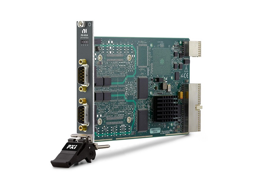
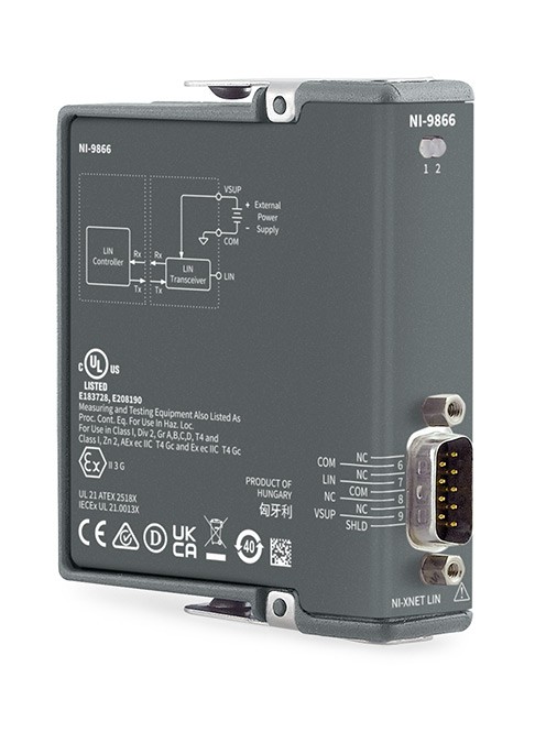
Figure 4. NI-XNET Platform for CAN, LIN, and FlexRay
NI USB LIN
Figure 5. NI USB-8476 LIN Interface
You can also communicate with LIN devices using the a USB LIN Interface Device. This is a lower cost, mobile solution for communicating to LIN networks.
Additional LIN Information
For more information on LIN specifications, visit the LIN consortium at www.lin-subbus.org.