From Friday, April 19th (11:00 PM CDT) through Saturday, April 20th (2:00 PM CDT), 2024, ni.com will undergo system upgrades that may result in temporary service interruption.
We appreciate your patience as we improve our online experience.
From Friday, April 19th (11:00 PM CDT) through Saturday, April 20th (2:00 PM CDT), 2024, ni.com will undergo system upgrades that may result in temporary service interruption.
We appreciate your patience as we improve our online experience.
With an exciting and innovative idea for a new device, you may be tempted to skip paper design altogether and just start on a physical prototype right away. Resisting this temptation will save you time and wasted effort in the long run. The time you invest in paper design pays big dividends later and helps you avoid many common pitfalls in the design process. Paper design does not mean writing out your detailed design for your prototype on paper with a pen or pencil. Paper design is creating a plan before doing any software coding or hardware design. Some of the benefits of paper design include getting ideas out of your head and onto paper, failing early instead of later, and getting early customer feedback.
How do you go from a great idea and a back-of-the-napkin sketch to a detailed paper design? The first step is to clearly define your goals by making a list of user requirements. These requirements should be as specific as possible. Research is crucial at this early stage to be sure you can meet your outlined requirements. Is your design feasible? Will it realistically be able to meet your requirements? Make sure that you distinguish between needs and wants for your design. As an innovator, you may be tempted to add advanced but not completely necessary features to your prototype. Know your objectives and stick to them.
With abstraction, you can describe an application without defining how to write the application. Abstraction generalizes the application to a high conceptual level. The two main types of abstraction are procedural and data. Procedural abstraction separates what a procedure accomplishes from how the procedure is implemented. Data abstraction separates the data you want to store from the physical means of storing the data. To assist with abstraction, remove key verbs and nouns from your system requirements document. From these verbs and nouns, you can determine what your program needs to accomplish and the objects that will be a part of your user interface. The verbs and nouns also help you determine the hardware components you need to complete your prototype.
Once you have a set of abstracted components you have gleaned from your device requirements, you can use a flowchart to move from abstracted components to a software design. Flowcharts help you develop a good understanding of the application flow by dividing the application into more manageable pieces. LabVIEW is a graphical programming development environment designed specifically to accelerate the productivity of engineers and scientists, which makes it an ideal tool for quickly converting your paper design to code. Since a LabVIEW block diagram is similar to a flowchart, moving from the flowchart to software code is a quick process.
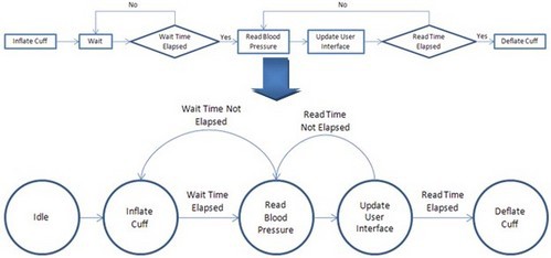
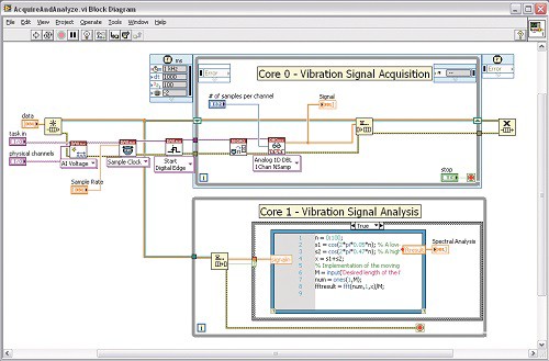
Figure 1. In this image of the flowchart, state diagram, and state machine for a blood pressure monitor, note that the five states defined in the state diagram are implemented in the state machine.
A state diagram is a specific type of flowchart that indicates the states of a program and the transitions between states. Each state satisfies a condition, performs an action, or waits for an event. The transitions between the states are conditions, actions, or events that cause the program to move to the next state. State diagrams are useful for prototyping because almost all embedded systems use a state architecture. That is, they are designed with the understanding that the prototype is always in a given state, even if that state is idle.
In LabVIEW, a state machine consists of a Case structure, While Loop, and shift register. An initial case is specified outside the loop. Each state from your state diagram corresponds to one case in the Case structure. Each case contains code that implements one state and logic that defines the transition to other cases. This architecture gives you the ability to scale your application by adding more cases and logic to the state machine.
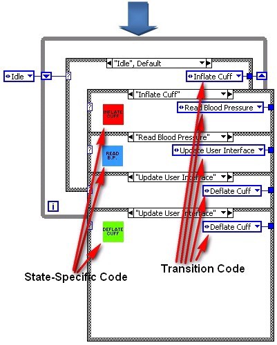
Often the best time to prototype a user interface (UI) is as you transition your paper design to software. Prototyping a UI helps you think through design architecture and application requirements as you make this transition. Sometimes even more importantly, it provides a tangible demonstration of device functionality for potential customers and investors. The more complex your prototype, the more valuable a UI prototype becomes in building support and gathering feedback for your design. Finally, it creates the big picture that prototype designers can rally around in designing features and adding functionality to the prototype. These UI prototyping advantages can save you money, decrease development time, and ultimately result in a better product.
Figure 2. UI Designed in LabVIEW (Obtain the code from the UI Interest Group.)
LabVIEW has a built-in front panel, which makes it an ideal tool for quickly developing a highly customizable UI. LabVIEW helps you easily add functionality as you churn through the design and prototyping cycle, which minimizes rework while you iterate on your design. With LabVIEW, you can quickly prototype your UI, modify it throughout the prototyping process, and even deploy it in a finished product.
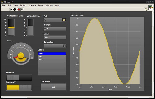
In LabVIEW, you can create all the required inputs and outputs and design a front panel before you write a single line of code or even finalize your application architecture. This mock-up of your UI is useful in determining which inputs and outputs you really need, and you can use it to refine requirements documents.
Figure 3. UI Mock-Up in LabVIEW
The next step in prototyping a UI is adding functionality to your mock-up to allow users to interact with the front panel, click through menus, adjust controls, and see results based on sample data sets or random number generation. The beauty in this approach is that you are prototyping a UI as well as defining your software design structure. If you do both well, you can build on the structure throughout the rest of the prototyping process.
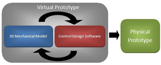
Virtual prototyping is the innovative methodology of combining mechanical modeling and simulation with control design to increase the efficiency of designing and prototyping embedded control systems and devices. With virtual prototyping, you can connect your software design and control algorithms to your 3D CAD mechanical models to test the mechanics of your system before even building your first physical prototype.
Figure 4. The Method of Virtual Prototyping
Virtual prototyping lowers the risks associated with machine design by improving the understanding of customer requirements, speeding up the design process, and streamlining debugging. Without a virtual prototype, you would have to build the entire physical prototype before you could obtain tangible customer feedback on the product’s operation. By using virtual prototyping, you can show a digital representation of the mechanics of the machine to the customer and get feedback more quickly before actually building the machine. This ensures that customers are more involved in the design process and prevents you from having to wait until it is too late in the prototyping process to get customer feedback.
Additionally, you can shorten the time to market of your product by creating a virtual prototype. This type of prototype helps you conceptualize and iterate on a virtual design, so that when you start to build a physical prototype, you get it right the first time. By being able to connect control software to a 3D CAD model, you can find and fix problems that you do not normally catch before building the physical prototype. You can write motion control code such as 2D and 3D motion profiles and see the result of the code on the 3D model. If a part is so large that it might cause a collision or if you want to look at the difference between a contour move and a linear move, you can fix the problem and view the difference with virtual prototyping. Compared to the traditional design approach, virtual prototyping helps you make key design decisions earlier in the process.
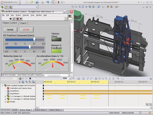
You can use LabVIEW graphical programming and motion tools with SolidWorks to help you build a virtual prototype of your machine. With LabVIEW, you can directly connect to SolidWorks mechanical models to build a virtual prototype of your system. By combining SolidWorks motion analysis capabilities with the LabVIEW SoftMotion Module, you can drive the simulation within SolidWorks to create realistic simulations of motion control systems.
Figure 5. LabVIEW SoftMotion Module and SolidWorks Integration
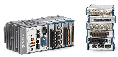
Finally, you can deploy the motion control application you developed and validated using SoftMotion and the SolidWorks 3D CAD model to embedded motion control platforms such as CompactRIO hardware, which includes a real-time processor and a user-programmable FPGA. Using CompactRIO, you can apply the algorithms to a physical prototype or the final machine. Because of this, you can reuse the code developed and tested within the simulation and connect that software code quickly to physical I/O and motors using NI hardware.
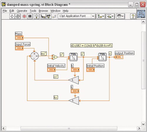
In addition to being able to build a virtual prototype with LabVIEW and SolidWorks tools, you can use LabVIEW to simulate any mechanical system. With the LabVIEW Control Design and Simulation Module, you can analyze open-loop model behavior, design closed-loop controllers, simulate online and offline systems, and conduct physical implementations.
Figure 6. LabVIEW Control Design and Simulation Tools
You can create models from first principles using transfer function, state-space, or zero-pole-gain representations. Additionally, you can interactively analyze the open- and closed-loop behavior of these models with time and frequency analysis tools, such as time step response or Bode plot. Use built-in tools for both multiple input, multiple output (MIMO) and single input, single output (SISO) systems and take advantage of simulation capabilities to verify linear and nonlinear system dynamics. You can also use built-in tools to convert your models developed in The MathWorks, Inc. Simulink® software to work with LabVIEW.
Adding I/O to your prototype is essential in creating a truly functional system. By adding sensory input and control output, you prove that your design works and can be implemented in the real world. Creating a paper design, implementing that design in software, and even simulating the design in a virtual environment are still largely conceptual exercises. To prove the value of your design to skeptical investors, you need a functional design that exists in and interacts with the real world. Data from prototyping operations also helps you refine functional requirements with clients and the rest of the design team based on actual performance.
The low-level knowledge required to integrate a sensor into a system from scratch and take meaningful data from it represents an often unforeseen time and resource expenditure. The custom nature of traditional sensor integration means costly rework for each design change. And design changes do tend to happen, especially when sensors are concerned, because translating specifications to make sure they match the needs of your prototype can be a challenge in itself.
Adding I/O to your prototype can be a daunting task. It’s often the sticking point in the prototyping process because of the difficulty in predicting the total cost of the time and resources needed to construct a custom I/O solution.
Overcoming the traditional difficulties in prototyping with I/O requires a paradigm shift in approach, especially for domain experts who need to efficiently prototype devices but may not have the specialized resources to overcome low-level sensor interface problems.
NI tools help you overcome these roadblocks by providing that paradigm shift in integrated hardware and intuitive graphical software, reconfigurable I/O devices, and the necessary IP and support systems you need to be successful.
Figure 7. By combining CompactRIO and modular, hot swappable C Series I/O modules with built-in signal conditioning, you can add I/O to your prototype quickly.
Successfully integrating sensor input and control output into a functional prototype is a huge step forward on the path to deployment and mass production. This step proves that you have overcome some of the biggest challenges in the product design process.
Algorithm engineering is a term coined for applied algorithm design. It refers to the process of transforming a pencil-and-paper algorithm into a robust, well-tested, and easy-to-use implementation. Implementing an algorithm to provide desired functionality in a prototype can be the most challenging part of the whole product development life cycle, but it also has the potential to be the most rewarding. By applying real-world I/O, you can see the functionality of your algorithm come to life before your eyes.
Implementing algorithms in a functional prototype can be difficult for a variety of reasons:
Programming limitations—Often control systems or processors that are chosen for their I/O capabilities, such as FPGAs, involve programming limitations for a developer. Programming for different platforms usually requires programming knowledge that few system-level designers have.
Basic algorithm implementation—Implementing low-level algorithms for basic functionality takes time. Speed is paramount in prototyping, and designers often cannot afford to get bogged down in implementing a well-known algorithm from scratch due to the lack of existing code.
Reworking algorithms for multiple platforms—As the functional prototype evolves, algorithms often have to be revisited to port them to a different type of system. Code is rarely functional between different run-time environments, and that makes scaling an application from prototyping to deployment difficult.
Test and verification—You usually don’t know for sure whether a system can meet functional requirements until late in the game, and starting over costs too much. For example, the processor may not be able to perform the required number of parallel tasks fast enough. It may not be able to achieve an adequate cycle time. It also may not be able to handle the processor-intensive analysis in real time.
LabVIEW graphical system design addresses and mitigates many of the potential pitfalls involved in engineering algorithms for a functional prototype. Graphical system design is an approach to solving design challenges that blends intuitive graphical programming and flexible commercial off-the-shelf (COTS) hardware. With this approach, you can use a single environment across all stages of design. Now take a more in-depth look at how this approach specifically addresses the challenges raised above.
One of the virtues of graphical system design is that it gives programmers the ability to create their algorithms regardless of the model of computation (MoC) they are implemented with. As code complexity for algorithms continues to grow, programmers have to use different MoCs to expand their coding capabilities. The following are just a few MoCs you can use with graphical system design:
Data flow—Data flow is the MoC most often associated with LabVIEW software. With data flow, operations require the developer to insert data in all the inputs before it executes. Data flow is an intuitive coding structure that makes implementing applications such as parallel processes easy.
Textual math—Textual math is another tool for creating complex functions easily. Text-based math is a human-readable implementation of often complex algorithms that are easier to write in a script description form. Examples of textual math are the formula node and LabVIEW MathScript RT Module. With LabVIEW MathScript, you can choose the most effective syntax for algorithm development, whether you are developing algorithms, exploring signal processing concepts, or analyzing results.
Figure 8. Reusing Text-Based Code With the LabVIEW MathScript RT Module
C code—Sometimes the algorithm you use was originally created in C or C++. In this case, you no longer have to discard the previous work. You can instead use the Inline C Node or the Call Library Function Node to directly call your previous code within LabVIEW. Use the Inline C Node for preexisting C code or implementing a small numeric or array algorithms and use the Call Library Function Node to access C code in DLLs or shared libraries.
Over the years, the LabVIEW platform has seen wide-scale adoption in numerous design disciplines, which has led to a need to incorporate data with different design and simulation tools. LabVIEW accomplishes this intercompatibility with numerous integration tools, libraries, and file formats. LabVIEW also offers standard integration with a large array of other software tools and measurement resources including the following:
Using these tools, integration with data from almost every kind of measurement and control device is possible. By combining LabVIEW with general-purpose standards for hardware communication, developers can ensure compatibility and scalability for many years in the future.
The hundreds of functions in LabVIEW that cover a wide variety of traditional algorithms in math, signal processing, probability, and control are essential building blocks for any custom algorithm. These functions alleviate the burden of writing low-level code and give engineers the time to focus on a solution instead of implementation.
Because using LabVIEW makes acquiring real-world data so easy, engineers find it valuable to test their algorithms with actual data as an iterative approach to tuning them. With this interactive test approach, you can experiment with different functions to see if they provide the required expected result. For example, when processing a signal with a filter, you can select from a wide variety of solutions, acquire the actual signal that you need, and look at the results in either a graph or file. If the results are not suitable for the application, then you can select another filter. Often it is easier to acquire the actual signal to apply to an algorithm and then take the time to simulate it on software.
Figure 9. NI ships LabVIEW with hundreds of built-in algorithms that you can use in your prototype.
One purpose of a prototype is to quickly demonstrate an idea and a design to potential customers, investors, and colleagues. Another and equally important reason to prototype is to test and validate a design for basic software and hardware performance. Often problems become apparent only when you combine the electrical, software, and mechanical components of a functional prototype.
By thoroughly testing in the prototyping stage, you can spot problems early before they represent a large sunk cost and fixing them becomes unrealistic. Prototype testing provides concrete evidence to back up performance claims and results in a more reliable final product that you can confidently take to deployment.
Software-defined instruments are inherently flexible and easily automated. Because of this, today’s product design teams can streamline their development processes by reducing the number of hours consumed in manual testing and by minimizing the amount of instrumentation required in the lab.
With the LabVIEW graphical software platform, you can set up simple programs to test the quality and reliability of the main algorithm. When prototyping, pay attention to the following two main aspects of testing:
Limit testing—Make sure that the software design provides quality data at the I/O channels throughout a range of data points. This helps keep the prototype within quality specifications throughout the product development cycle.
Stress testing—Make sure the quality specifications are met for long periods of exposure and when all the I/O channels get pushed to the limits at the same time. The algorithm needs to be robust enough to take care of situations where there is an overload of data being processed.
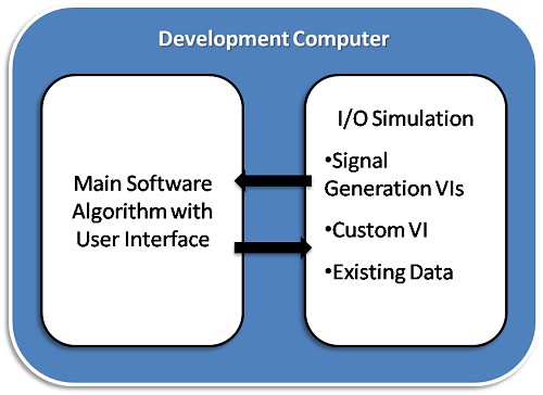
Test without hardware by using simulation VIs to stretch the software algorithm to the limits. You can do this in LabVIEW by using a variety of signal generation VIs or by developing a VI that accurately depicts your actual I/O.
Figure 10. I/O Simulation Methods
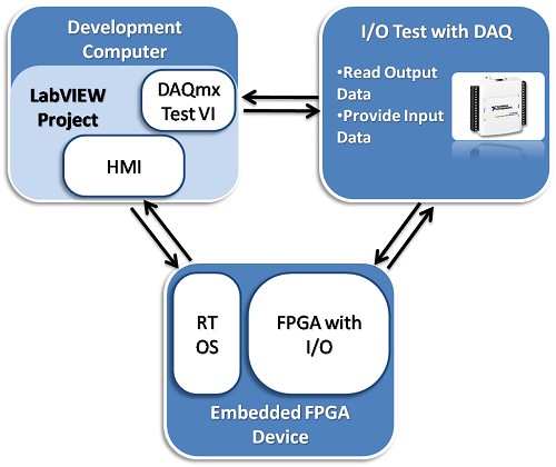
Software testing can be limited because it does not provide the same feel of using real-world hardware. With LabVIEW, you can use COTS hardware to perform real-world I/O testing.
You can debug physical hardware I/O by using a digital multimeter or a data acquisition device. LabVIEW combined with the NI-DAQmx driver provides an easy-to-use, high-level interface to perform complex data acquisition tasks with DAQmx Express VIs.
Figure 11. Testing With NI DAQ Hardware
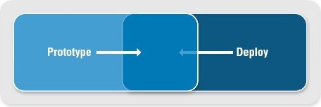
Progressing through the design process from an idea to a paper design to a functional prototype and finally to a releasable product can be challenging, so you need to find ways to ease the transition between these stages. The ideal situation is to design a prototype that you can actually deploy, which means you can produce and distribute it in high volumes. This does not often happen in practice, but by designing and prototyping with deployment in mind, you can make sure that the key components of your design endure through to deployment. The key is finding the right tools and platform that not only give you the flexibility and capabilities necessary to effectively prototype but are also powerful and customizable enough to take to market.
Figure 12. Having a prototype that comes close to matching the final product is ideal.
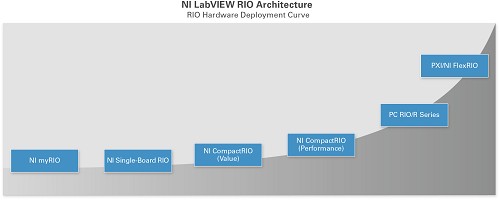
The LabVIEW reconfigurable I/O (RIO) architecture is an integral part of the NI graphical system design platform. A modern approach to designing, prototyping, and deploying monitoring and control systems, graphical system design combines the open LabVIEW graphical programming environment with COTS hardware to dramatically simplify development, which results in higher quality designs and the ability to incorporate custom design.
The LabVIEW RIO architecture is based on four components: a processor, a reconfigurable FPGA, modular I/O hardware, and graphical design software. Combined, these components give you the ability to rapidly create custom hardware circuitry with high-performance I/O and achieve unprecedented flexibility in system timing control. Many NI products incorporate this architecture.
Figure 13. NI offers products featuring the LabVIEW RIO architecture to provide maximum flexibility, reliability, and performance.
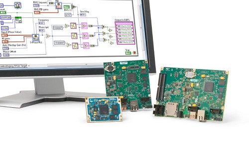
Single-Board RIO controllers are highly customizable single printed circuit boards that offer the most flexibility. You provide the I/O terminals, power supply, and enclosure. Single-Board RIO allows for seamless user integration into the final product. If you need even more flexibility or a more compact size, the NI System on Module (SOM) provides those for your design.
Figure 14. Single-Board RIO and SOM controllers offer maximum flexibility.
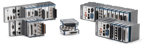
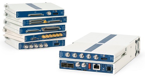
If you have more rugged needs, CompactRIO hardware is the best option. This industrial-level hardware is capable of taking a great deal of punishment. If you need a device that can handle high levels of shock and vibration and you do not want to spend the time and money to develop your own controller to perform under these harsh conditions, consider CompactRIO. Beyond its ruggedness, the CompactRIO platform does not require the customization needed by Single-Board RIO devices. CompactRIO is also a good solution if you don’t want to handle your own power conversion, enclosure, or I/O terminals.
Figure 15. CompactRIO controllers offer maximum ruggedness.
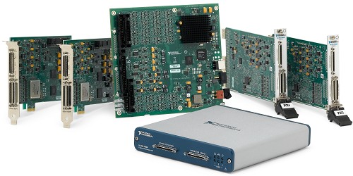
For more precise measurements, such as in a laboratory environment, or for when you are limited by a PC-based platform, R Series multifunction RIO devices are an effective option. Available in PCI, PCI Express, USB, PXI, and PXI Express form factors, these devices offer superior I/O signal conditioning and accuracy compared with Single-Board RIO and CompactRIO. R Series devices deliver the power of the LabVIEW RIO architecture to help you expand your capabilities more than you can with traditional data acquisition solutions.
Figure 16. R Series data acquisition adds LabVIEW FPGA to standard PC form factors.
If you need ultrahigh-performance I/O with speeds up to 3 GS/s analog or 1 Gb/s digital, then FlexRIO is the best option. Whether you are looking to minimize your cost of test or speed up the development of your next embedded system, FlexRIO offers the fastest I/O and largest FPGAs in the LabVIEW RIO architecture to help you tackle some of the most complex prototyping or deployment challenges.
Figure 17. FlexRIO controllers and modules offer maximum FPGA and I/O performance.
The LabVIEW RIO architecture not only offers a multitude of form factor options but also shares a common platform. This means you can use the same code and processes for any product supported by the LabVIEW RIO architecture and switch between them if necessary. In fact, when switching between Single-Board RIO, CompactRIO, R Series, or FlexRIO, you can reuse most of your code. Even if you are not fully aware of all of the requirements for the final product, a mistake when choosing a prototyping platform does not result in a complete rewrite of all of your code. This allows the prototyping process to begin sooner, which speeds up development time. You can also start your prototype with CompactRIO and move to Single-Board RIO for deployment with a minimum amount of mechanical rework and almost no software changes. Again, this is possible because of the shared platform.
Prototyping is a crucial part of the embedded design process. The ability to demonstrate a functioning idea to investors, customers, and management is a great way to get your idea into someone's budget. NI graphical system design tools have proven useful for getting a functional prototype working quickly without requiring a large design team. Taking advantage of these steps to create a quality functional prototype can give you a jump-start on your next application.
Simulink® is a registered trademark of The MathWorks, Inc.