Introduction to Modbus using LabVIEW
Overview
Contents
- The Request-Response Cycle
- The Modbus Data Model
- Modbus Function Codes
- LabVIEW Modbus API
- Modbus I/O Servers
- NI OPC Servers With OPC I/O Servers or OPC UA
- Related Links
Introduction to Modbus
Modbus is typically used for Supervisory Control and Data Acquisition (SCADA)-style network communication between devices. For example, a large server may be used to master a programmable logic controller (PLC) or programmable automation controller (PAC), while that PLC/PAC may in turn master a sensor, valve, motor, or any other embedded device.
To meet these needs, Modbus was designed as a request-response protocol with a flexible data and function model—features that are part of the reason it is still in use today.
The Request-Response Cycle
The Modbus protocol follows a master and slave architecture where a master transmits a request to a slave and waits for the response. This architecture gives the master full control over the flow of information, which has benefits on older multidrop serial networks. Even on modern TCP/IP networks, it gives the master a high degree of control over slave behavior, which is helpful in some designs.
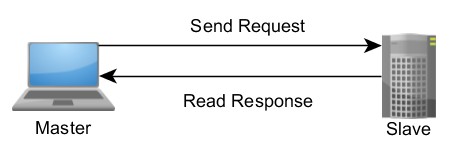
Figure 1. The Master-Slave, Request-Response Relationship of Modbus Devices
In Modbus, this request is a layered set of data. The first layer is the application data unit (ADU), which is what most people consider to be the “type” of Modbus used. There are three ADUs: ASCII, remote terminal unit (RTU), and TCP/IP.
TCP is a modern format that allows for efficient handling of Modbus requests and responses in software, as well as more efficient networking through the use of dedicated connections and identifiers for each request. RTU and ASCII are older serial ADU formats with the primary difference between the two being that RTU uses a compact binary representation while ASCII sends all requests as streams of ASCII characters.
For most applications, the preferred ADU depends on the desired physical network (Ethernet, serial, or something else), the number of devices on the network, and the ADUs supported by the master and slave devices on the network. From the point of view of the application using Modbus, data should simply be exposed as if the ADU did not exist.
Within each ADU, there is a protocol data unit (PDU) that is the core of the Modbus protocol. Each PDU contains a function code and associated data. Each function code has a well-defined response, and you can think of this function code as the command being sent to the slave.
In some cases, errors can occur. Modbus defines a specific PDU for exceptions, which lets the master know what happened. Most drivers convert this to a form that makes sense for the language or application in use.
The Modbus Data Model
Modbus manages the access of data simply and flexibly. Natively, Modbus supports two data types: a Boolean value and an unsigned, 16-bit integer.
In SCADA systems, it is common for embedded devices to have certain values defined as inputs, such as gains or proportional integral derivative (PID) settings, while other values are outputs, like the current temperature or valve position. To meet this need, Modbus data values are divided into four ranges (see Table 1). A slave can define as many as 65,536 elements in each range.
| Memory Block | Data Type | Master Access | Slave Access |
| Coils | Boolean | Read/Write | Read/Write |
| Discrete Inputs | Boolean | Read-only | Read/Write |
| Holding Registers | Unsigned Word | Read/Write | Read/Write |
| Input Registers | Unsigned Word | Read-only | Read/Write |
Table 1. Modbus Data Model Blocks
In many cases, sensors and other devices generate data in types other than simply Booleans and unsigned integers. It is common for slave devices to convert these larger data types into registers. For example, a pressure sensor may split a 32-bit floating point value across two 16-bit registers.
Modbus exposes these values in a completely conceptual way, meaning they may not actually exist in memory. For example, a slave device may be defined such that holding registers and input registers actually share the same memory if that behavior makes sense for the slave. In most cases, slaves store each type of data that it supports in separate memory, and limits the number of data elements that a master can access. This flexibility is an option because of the way data is exposed through the well-defined behavior of Modbus function codes.
Modbus Function Codes
Modbus function codes determine how data is accessed and modified by the master. Unlike the data ranges, which are conceptual, function codes have a well-defined behavior. When a slave is asked to perform a function code, it uses the parameters of the function to execute that well-defined behavior. Figure 2 shows this link between a function request and the actual memory of the device.
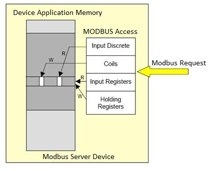
Figure 2. The Mapping Between a Function Code, Data Ranges, and the Actual Memory of a Slave Device
The most common function codes are named after the conceptual data range they modify or access. For example, “read holding registers” takes the action of pulling data out of the memory defined as holding registers and returning it to the master. Table 2 identifies the most common function codes.
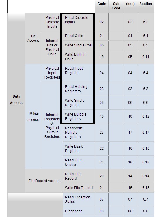
Table 2. Common Function Codes
Getting Started With Modbus in LabVIEW
NI provides three primary mechanisms for interfacing with Modbus devices: (1) a high-level OPC server, (2) a Modbus I/O server, and (3) a low-level Modbus API introduced in NI LabVIEW 2014 software through the LabVIEW Real-Time or LabVIEW Datalogging and Supervisory Control (DSC) modules.
LabVIEW Modbus API
The low-level Modbus API is the preferred option when your application needs a high level of control over the sequencing and timing of Modbus requests. The low-level API is typically also the preferred choice where flexibility is paramount. In contrast, the flexibility and power offered by the LabVIEW Modbus API also means that your application code must be more complex to correctly manage the API. To help you understand this complexity, LabVIEW provides two examples.
Modbus Introductory Example
The first example, Modbus Library.lvproj, provides a basic overview of the API’s functionality. It also demonstrates the differences between an implementation on a PC and a real-time target. Figure 3 shows the code involved in the Real-Time Modbus Master example.
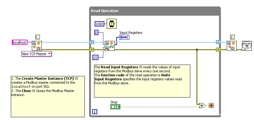
Figure 3. Master on RT Target.vi
This example demonstrates the core requirements of a Modbus application using the LabVIEW API. First, a Modbus instance is created. In this case, a TCP master. However, you can switch this example to a serial master by changing the polymorphic instance selector.
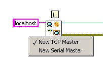
Figure 4. Changing the Type of Modbus Master
When the instance is created, you can begin polling the slave device for data. The example shows the use of the function code Read Input Registers. All Modbus function codes supported by the API are shown on the appropriate palette. Because of implementation of the protocol, the slave API has additional functions that the master cannot implement. For example, a slave can write to the input register range, while a master may only read from that range. Figure 5 shows the function codes.
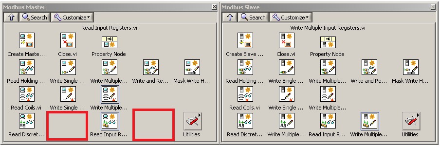
Figure 5. Modbus Master and Slave Palettes Showing the Function Codes
Finally, the Modbus instance is closed, de-allocating the memory associated with the instance. This also closes any references, including the TCP connection or NI-VISA serial references used by the instance.
Only the master example has been discussed thus far; however, every example follows the same basic pattern familiar to most LabVIEW users: open, read/write, and close.
Finally, although the API does look the same, it is important to understand the key difference. If your device is a master, it must send a request across the network to the appropriate slave to acquire data. The slave, on the other hand, has its own local data storage and can access it quickly.
Redundant Master Example
The basic example may suffice for some applications; however, it may not be enough for complicated applications where the goal is to talk to a sensor or gateway. To help bridge this gap, a sample application shows how to use two masters to communicate with a given slave. If one of the masters fails and loses connection with either the slave or human machine interface (HMI), the other master takes over.
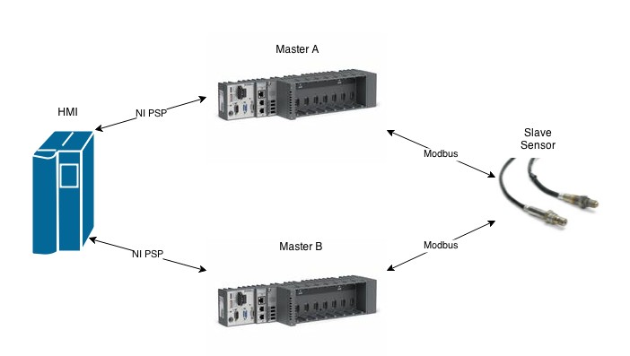
Figure 6. Design of the Redundant Master Example
If this design meets the needs of your application, or if you are interested in a more complex example of Modbus communication, view Redundant Modbus Masters.lvproj in the Example Finder.
Modbus I/O Servers
Modbus I/O servers, which are in the LabVIEW DSC and LabVIEW Real-Time modules, provide a high-level engine for communicating over Modbus. Rather than specifying a function code that you wish to send, you register the set of data you would like to access and the I/O server schedules the requests automatically at the specified rate.
To use I/O servers, you add a new I/O server to the desired target in your project. As with the low-level API, you can choose between a Modbus master or slave, and these lead to additional parameters. For example, a master has a defined polling rate—the rate at which every request is sent to the slave, while slaves must wait on those requests and have no predefined timing.
After the I/O server is created, you may specify the items on the device you wish to read. Unlike the low-level API, where you must generate and process the requests yourself, Modbus I/O servers let you select from a wide variety of formats and data types. For example, you can read the holding register at address 0 by mapping a variable to the item 400001, read the first bit of this register by selecting 400001.1, and read the single precision float that is stored in registers 0 and 1 by selecting F400001.
After selecting variables to access, you can read or write these variables using shared variable nodes on the block diagram. You can even alias the variable names.
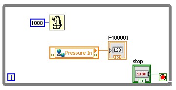
Figure 7. A Simple I/O Server Application
The programming effort involved with an I/O server application is minimal and easier to understand. Remember that this ease of use comes with limitations. Data updates at only the predefined rate, and there is no way to add or remove requested data at run time. If these limitations are acceptable for your application, I/O servers are the recommended cross-platform option.
For more information and a step-by-step guide, view Connect LabVIEW to Any PLC With Modbus.
NI OPC Servers With OPC I/O Servers or OPC UA
For complicated applications involving many slave devices that communicate over different protocols, the standard Modbus I/O might not suffice. A common solution is to use an OPC server, which acts as a data aggregator for all of your systems, and then use the OPC I/O servers included in the LabVIEW DSC Module to communicate with that OPC server.
Figure 8 shows an example of this architecture, with NI OPC Servers using Modbus to communicate directly with sensors and OPC UA to communicate with an CompactRIO Controller. After data is aggregated in NI OPC Servers, an OPC I/O server can retrieve data and share it with the LabVIEW application.
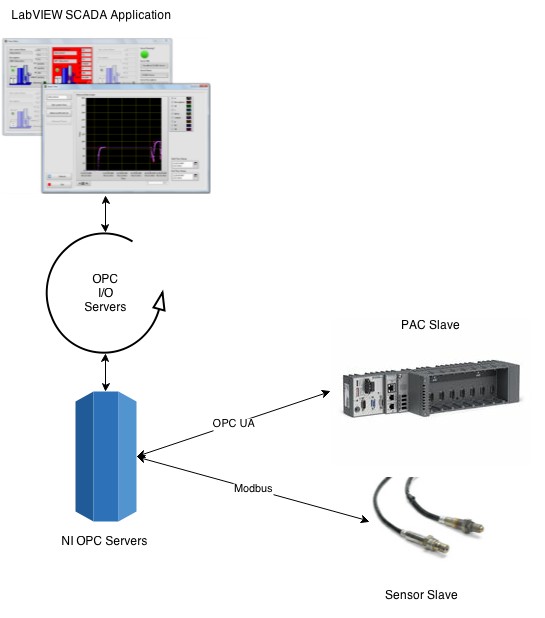
Figure 8. A SCADA Application Using Modbus, NI OPC Servers, and OPC I/O Servers
You can also develop a similar architecture that uses the OPC UA Toolkit (OPC UA functionality was included in the LabVIEW DSC Module before version 2017) in place of OPC I/O servers. However, the OPC UA driver is a low-level driver and does not provide the ease of use afforded by OPC I/O servers.
To develop an application like this, you must first generate a valid configuration for NI OPC Servers to communicate with your slave devices. This is done by generating channels—which define a driver configuration—and devices—which define an individual endpoint for that driver. After you have configured a device, you can then generate tags.
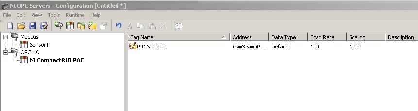
Figure 9. A Sample Configuration in NI OPC Servers for the Above Architecture
And after you have configured NI OPC Servers, you can configure an OPC I/O server to communicate with these tags. While Modbus I/O servers are configured to access registers, OPC I/O servers are configured to access tags in the OPC server.
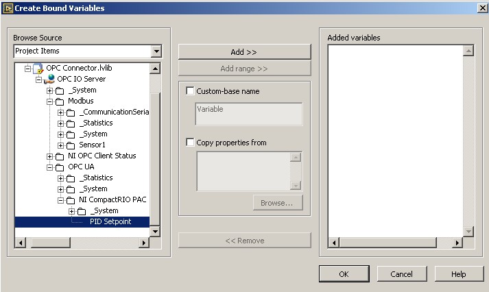
Figure 10. Configuring OPC I/O Servers
This binding process generates variables you can then use in your application.
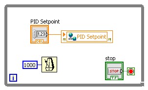
Figure 11. A Simple Application Using OPC I/O Servers
Find a full walkthrough of this process at Connect LabVIEW to Any PLC Using OPC.
Meeting the Needs of Your Application
Modbus is a simple protocol that you can use in various ways to implement powerful applications.
For Modbus communication, NI provides three primary options that provide a wide array of functionality to meet the needs of your application. First, a low-level API provides fine control over the protocol, with high performance, at the expense of ease of use. Everything must be done manually when using the low-level API. For simpler monitoring applications, Modbus I/O servers provide a simpler and easier API for accessing or serving up Modbus data. In exchange for ease of use, I/O servers give up the tight control over the protocol that can be required for some applications. Finally, for large and complex systems, it may be beneficial to consider a full-featured OPC server to serve as a data aggregator. Then, simply use a tool like the LabVIEW OPC UA Toolkit or OPC I/O servers to provide your application access to this data.