From Friday, April 19th (11:00 PM CDT) through Saturday, April 20th (2:00 PM CDT), 2024, ni.com will undergo system upgrades that may result in temporary service interruption.
We appreciate your patience as we improve our online experience.
From Friday, April 19th (11:00 PM CDT) through Saturday, April 20th (2:00 PM CDT), 2024, ni.com will undergo system upgrades that may result in temporary service interruption.
We appreciate your patience as we improve our online experience.
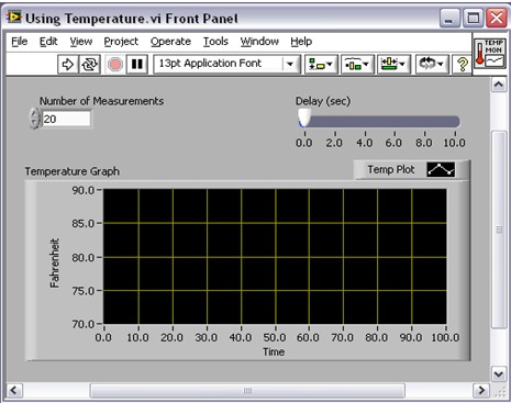
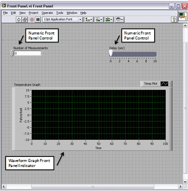
The front panel window is the user interface for the VI. The front panel has controls and indicators, which are the interactive input and output terminals, respectively, of the VI. Controls and indicators placed on the front panel are automatically placed on the block diagram. Refer to the “Block Diagram” tutorial for more information on block diagram terminals.
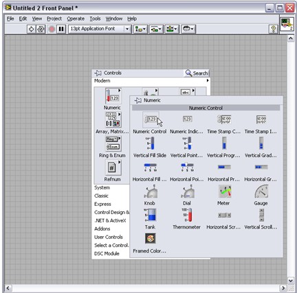
When you open a new or existing VI, the front panel window of the VI appears and functions as the graphical user interface or GUI of a VI. You can find the source code that runs the front panel on the block diagram. The front panel window contains a toolbar across the top and a Controls palette that you can access by right-clicking anywhere on the front panel.
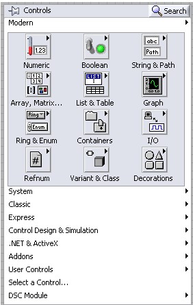
After opening the Controls palette, use it to place controls and indicators on the front panel.
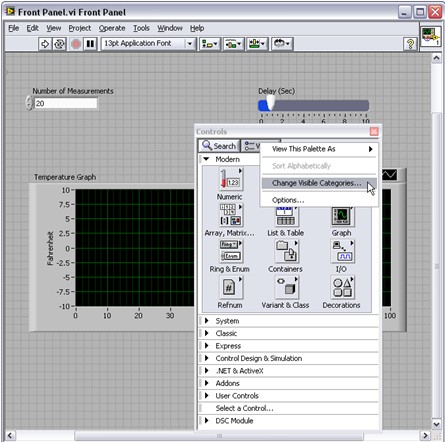
Note: Use the thumb tack to pin the Controls palette to the front panel and then select View»Change Visible Categories.
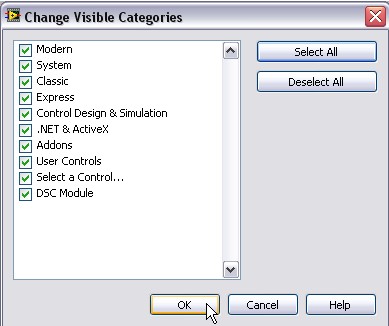
In the Change Visible Categories dialog box, click Select All and then OK to make all available controls and indicators visible on the front panel.
Controls – knobs, push buttons, dials, and other input devices – are the interactive input terminals, while indicators — graphs, LEDs, and other displays – are the interactive output terminals of the VI. Controls simulate instrument input devices and supply data to the block diagram of the VI. Indicators simulate instrument output devices and display data the block diagram acquires or generates.
The figure above has two controls – Number of Measurements and Delay (sec) – and one indicator, a waveform graph named Temperature Graph. The user can change the input value for the Number of Measurements and Delay (sec) controls. The user can see the value generated by the VI on the Temperature Graph indicator. The VI generates the values for the indicators based on the code created on the block diagram. To learn more about the block diagram, see the “Block Diagram” tutorial.
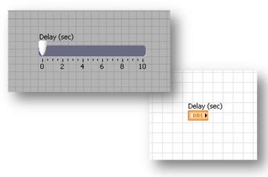
Every control and indicator has a data type associated with it. For example, the Delay (sec) horizontal slide is a numeric data type. Double-click the Delay (sec) control to make LabVIEW jump to the terminal location on the block diagram. Notice the color of the terminal. Orange terminals signify a data type called double (DBL), which is a type of numeric data.
The most commonly used data types are numeric, Boolean value, and string. Learn more about data types in the “Data Types” tutorial.
The numeric data type can represent various types of numbers, such as integer or real. The two common numeric objects are the numeric control and the numeric indicator. Objects such as meters and dials also represent numeric data. Use the Controls palette to place a numeric control on the front panel and then use the increment and decrement buttons to adjust its values.
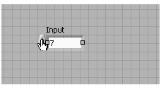
Follow steps 1-3 to create a numeric control and change its value.
1. Right-click the front panel to open the Controls palette, and from the Numeric subpalette drag and drop a Numeric Control onto the front panel.
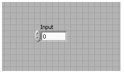
2. Label the control Input by double-clicking on the label and typing the word “Input.”
3. Now change the value of the control by clicking the increment or decrement button. Alternatively, you can double-click the number with either the Labeling tool or the Operating tool, enter a new number, and press the <Enter> key.
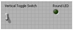
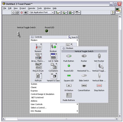
The Boolean data type represents data that has only two parts, such as TRUE and FALSE or ON and OFF. Use Boolean controls and indicators to enter and display Boolean values. Boolean objects simulate switches, push buttons, and LEDs. The vertical toggle switch and the round LED Boolean objects are shown below. You can find them in the Boolean subpalette in the Controls palette (see below).
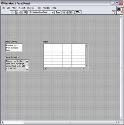
The string data type is a sequence of ASCII characters. Use string controls to receive text from the user, such as a password or user name, and use string indicators to display text to the user. The most common string objects are tables and text entry boxes as shown below. You can find string controls and indicators in the String and Path subpalette or the Lists and Tables subpalette. Some common string indicators are shown below.
All LabVIEW objects have associated shortcut menus and property dialog boxes. As you create a VI, use the shortcut menu items and/or the properties dialog box to change the appearance and/or behavior of front panel and block diagram objects. To access the shortcut menu, right-click the object you want to modify. To access the Properties dialog box, select Properties from the shortcut menu.
Follow steps 1 and 2 to create a string control and then use the Properties dialog box to add a scroll bar. Start with a blank VI.
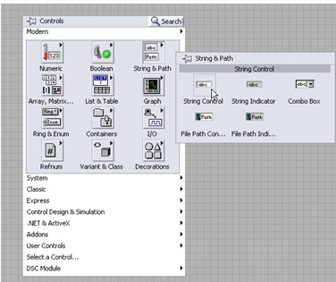
1. From the String & Path subpalette, select a String Control and place it on the front panel.
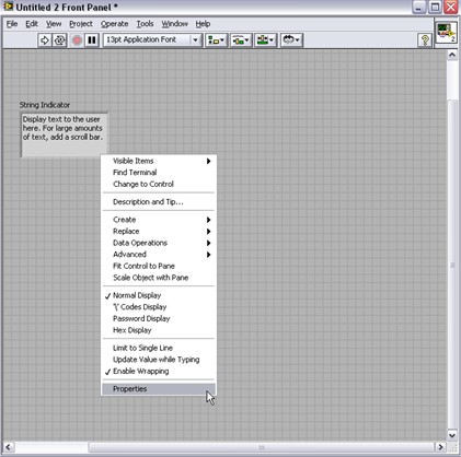
2. Right-click the string indicator to open the shortcut menu and select Properties.
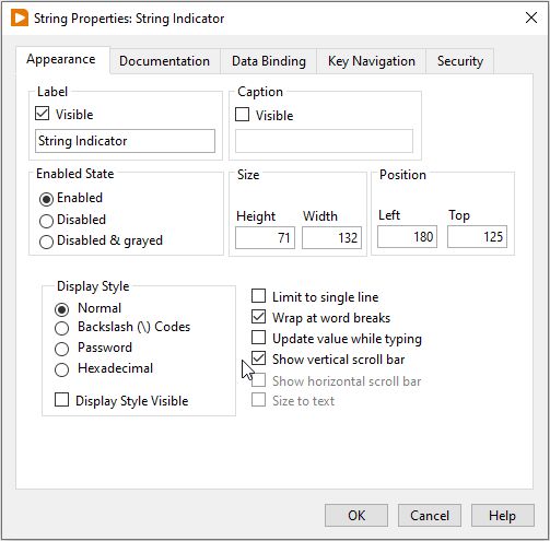
3. From the Properties dialog box, put a check in the Show vertical scroll bar checkbox and click OK.
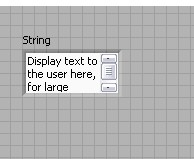
4. The resulting string control has a scroll bar so the user can scroll up and down to view all of the text. This allows the use of a small string control to display a large amount of text.
Each window has a toolbar associated with it. Use the front panel window toolbar buttons to run and edit the VI. The following toolbar appears on the front panel window.
Click the Run button to run your VI. You do not need to compile your code; LabVIEW compiles it automatically. You can run a VI if the Run button appears as a solid white arrow, shown at left.
The Run button appears broken when the VI you are creating or editing contains errors. If the Run button still appears broken after you finish wiring the block diagram, the VI is broken and cannot run. Click this button to display the Error List window, which lists all errors and warnings.
Click Run Continuously to run the VI until you abort or pause execution. You also can click the button again to disable continuous running.
While the VI runs, the Abort Execution button appears. Click this button to stop the VI immediately if there is no other way to stop the VI. If more than one running top-level VI uses the VI, the button is dimmed.
Caution: The Abort Execution button stops the VI immediately before it finishes the current iteration. Aborting a VI that uses external resources, such as external hardware, might leave the resources in an unknown state by not resetting or releasing them properly. Design VIs with a stop button to avoid this problem.
Click Pause to pause a running VI. When you click the Pause button, LabVIEW highlights on the block diagram the location where you paused execution, and the Pause button appears red. Click the Pause button again to continue running the VI.
Select the Text Settings pull-down menu to change the font settings for the selected portions of your VI, including size, style, and color.
Click the Align Objects pull-down menu to align objects along axes, including vertical, edge, and left.
Click the Distribute Objects pull-down menu to resize multiple front panel objects to the same size.
Click the Resize Objects pull-down menu to resize multiple front panel objects to the same size.
Click the Reorder pull-down menu when your objects overlap each other and you want to define which one is in front or back of another. Select one of the objects with the Positioning tool and then select from Move Forward, Move Backward, Move To Front, and Move To Back.
Click the Show Context Help Window button to toggle the display of the context help window.
Enter Text appears to remind you that a new value is available to replace an old value. The Enter Text button disappears when you click it, press the <Enter> key, or click the front panel or block diagram workspace.
Tip: The <Enter> key on the numeric keypad ends a text entry, while the main <Enter> key adds a new line. To modify this behavior, select Tools»Options, choose Environment from the Category list, and place a checkmark in the End text entry with Enter key option.
It is important for a VI to have an intuitive and easy-to-read front panel. The front panel is essentially the gateway for all user input and output of a VI. Therefore it is essential that the programmer has good grasp of how to effectively program a front panel.