Measuring Strain with Strain Gages
This document provides information to help you understand basic strain concepts, how strain gages work, and how to select the right configuration type. After you decide on your sensors, you can consider the required hardware and software to properly condition, acquire, and visualize strain measurements. You can also consider any extra signal conditioning you may need.
What is Strain?
In mechanical testing and measurement, you need to understand how an object reacts to various forces. The amount of deformation a material experiences due to an applied force is called strain. Strain is defined as the ratio of the change in length of a material to the original, unaffected length, as shown in Figure 1. Strain can be positive (tensile), due to elongation, or negative (compressive), due to contraction. When a material is compressed in one direction, the tendency to expand in the other two directions perpendicular to this force is known as the Poisson effect. Poisson’s ratio (v) is the measure of this effect and is defined as the negative ratio of strain in the transverse direction to the strain in the axial direction. Although dimensionless, strain is sometimes expressed in units such as in./in. or mm/mm. In practice, the magnitude of measured strain is very small, so it is often expressed as microstrain (µε), which is ε x 10-6.
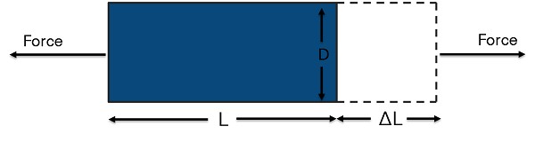

Figure 1. Strain is the ratio of the change in length of a material to the original, unaffected length.
The four different types of strain are axial, bending, shear, and torsional. Axial and bending strain are the most common (see Figure 2). Axial strain measures how a material stretches or compresses as a result of a linear force in the horizontal direction. Bending strain measures a stretch on one side of a material and the contraction on the opposite side due to the linear force applied in the vertical direction. Shear strain measures the amount of deformation that occurs from a linear force with components in both the horizontal and vertical directions. Torsional strain measures a circular force with components in both the vertical and horizontal directions.
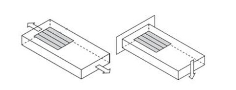
Figure 2. Axial strain measures how a material stretches or pulls apart. Bending strain measures a stretch on one side and a contraction on the other side.
Measuring Strain
Strain is commonly measured by a strain gage (sometimes written as “strain gauge”). A strain gage works by measuring its electrical resistance on the object subjected to an axial, bending, shear, or torsional force. Since electrical resistance varies in proportion to the amount of strain in the device as force is applied, it can be used to quantify strain. The most widely used strain gage is the bonded metallic strain gage. The metallic strain gage consists of a very fine wire or, more commonly, metallic foil arranged in a grid pattern. The grid pattern maximizes the amount of metallic wire or foil subject to strain in the parallel direction. The grid is bonded to a thin backing called the carrier, which is attached directly to the test specimen. Therefore, the strain experienced by the test specimen is transferred directly to the strain gage, which responds with a linear change in electrical resistance.
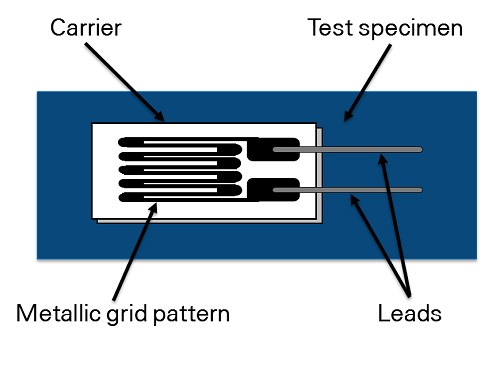
Figure 3. The electrical resistance of metallic grid changes in proportion to the amount of strain experienced by the test specimen.
A fundamental parameter of the strain gage is its sensitivity to strain, expressed quantitatively as the gage factor (GF). GF is the ratio of the fractional change in electrical resistance to the fractional change in length, or strain:
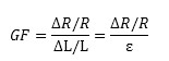
The GF for metallic strain gages is usually around 2. You can obtain the actual GF of a particular strain gage from the sensor vendor or sensor documentation.
In practice, strain measurements rarely involve quantities larger than a few millistrain (e x 10-3). Therefore, to measure the strain, you have to accurately measure very small changes in resistance. For example, suppose a test specimen undergoes a strain of 500 me. A strain gage with a GF of 2 exhibits a change in electrical resistance of only 2 (500 x 10-6) = 0.1%. For a 120 Ω gage, this is a change of only 0.12 Ω.
To measure such small changes in resistance, strain gage configurations are based on the concept of a Wheatstone bridge. The general Wheatstone bridge, illustrated in Figure 4, is a network of four resistive arms with an excitation voltage, VEX, that is applied across the bridge.
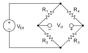
Figure 4. Strain gages are configured in Wheatstone bridge circuits to detect small changes in resistance.
The Wheatstone bridge is the electrical equivalent of two parallel voltage divider circuits. R1 and R2 compose one voltage divider circuit, and R4 and R3 compose the second voltage divider circuit. The output of a Wheatstone bridge, Vo, is measured between the middle nodes of the two voltage dividers.
From this equation, you can see that when R1 /R2 = R4 /R3, the voltage output VO is zero. Under these conditions, the bridge is said to be balanced. Any change in resistance in any arm of the bridge results in a nonzero output voltage. Therefore, if you replace R4 in Figure 4 with an active strain gage, any changes in the strain gage resistance unbalance the bridge and produce a nonzero output voltage that is a function of strain.
Choosing the Right Strain Gage
Types of Strain Gages
The three types of strain gage configurations, quarter-, half-, and full-bridge, are determined by the number of active elements in the Wheatstone bridge, the orientation of the strain gages, and the type of strain being measured.
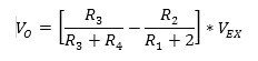
Quarter-Bridge Strain Gage
Configuration Type I
- Measures axial or bending strain
- Requires a passive quarter-bridge completion resistor known as a dummy resistor
- Requires half-bridge completion resistors to complete the Wheatstone bridge
- R4 is an active strain gage measuring the tensile strain (+ε)
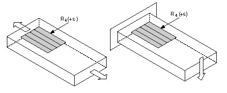
Figure 5. Quarter-Bridge Strain Gage Configurations.
Configuration Type II
Ideally, the resistance of the strain gage should change only in response to applied strain. However, strain gage material, as well as the specimen material to which the gage is applied, also responds to changes in temperature. The quarter-bridge strain gage configuration type II helps further minimize the effect of temperature by using two strain gages in the bridge. As shown in Figure 6, typically one strain gage (R4) is active and a second strain gage (R3) is mounted in close thermal contact, but not bonded to the specimen and placed transverse to the principal axis of strain. Therefore, the strain has little effect on this dummy gage, but any temperature changes affect both gages in the same way. Because the temperature changes are identical in the two strain gages, the ratio of their resistance does not change, the output voltage (Vo) does not change, and the effects of temperature are minimized.
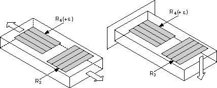
Figure 6. Dummy strain gages eliminate effects of temperature on the strain measurement.
Half-Bridge Strain Gage
You can double the bridge’s sensitivity to strain by making both strain gages active in a half-bridge configuration.
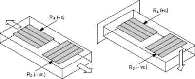
Configuration Type I
- Measures axial or bending strain
- Requires half-bridge completion resistors to complete the Wheatstone bridge
- R4 is an active strain gage measuring the tensile strain (+ε)
- R3 is an active strain gage compensating for Poisson’s effect (-νε)
This configuration is commonly confused with the quarter-bridge type II configuration, but type I has an active R3 element that is bonded to the strain specimen.
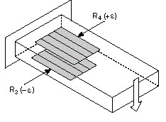
Configuration Type II
Measures bending strain only
Requires half-bridge completion resistors to complete the Wheatstone bridge
R4 is an active strain gage measuring the tensile strain (+ε)
R3 is an active strain gage measuring the compressive strain (-ε)
Figure 7. Half-bridge strain gages are two times more sensitive than quarter-bridge strain gages.
Full-Bridge Strain Gage
A full-bridge strain gage configuration has four active strain gages and is available in three different types. Types I and II measure bending strain and type III measures axial strain. Only types II and III compensate for the Poisson effect, but all three types minimize the effects of temperature.
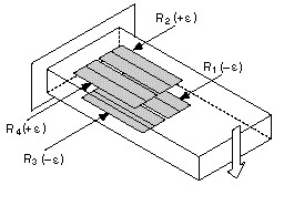
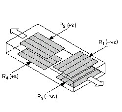
Configuration Type I: Only Bending Strain
- Highly sensitive to bending strain only
R1 and R3 are active strain gages measuring compressive strain (–e)
R2 and R4 are active strain gages measuring tensile strain (+e)

Configuration Type II
Measures bending strain only
Requires half-bridge completion resistors to complete the Wheatstone bridge
R4 is an active strain gage measuring the tensile strain (+ε)
R3 is an active strain gage measuring the compressive strain (-ε)
R4 is an active strain gage measuring the tensile strain (+e)
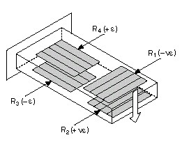
Configuration Type III: Only Axial Strain
Measures axial strain
R1 and R3 are active strain gages measuring the compressive Poisson effect (–νe)
R2 and R4 are active strain gages measuring the tensile strain (+e)
Figure 8. Full-Bridge Strain Gage Configurations
Specifications of Strain Gages to Consider
Once you have decided the type of strain you intend to measure (axial or bending), other considerations include sensitivity, cost, and operating conditions. For the same strain gage, changing the bridge configuration can improve its sensitivity to strain. For example, the full-bridge type I configuration is four times more sensitive than the quarter-bridge type I configuration. However, full-bridge type I requires three more strain gages than quarter-bridge type I. It also requires access to both sides of the gaged structure. Additionally, full-bridge strain gages are significantly more expensive than half-bridge and quarter-bridge gages. For a summary of the various types of strain gages, refer to the following table.
Grid Width
Using a wider grid, if not limited by the installation site, improves heat dissipation and enhances strain gage stability. However, if the test specimen has severe strain gradients perpendicular to the primary axis of strain, consider using a narrow grid to minimize error from the effect of shear strain and Poisson strain.
Nominal Gage Resistance
Nominal gage resistance is the resistance of a strain gage in an unstrained position. You can obtain the nominal gage resistance of a particular gage from the sensor vendor or sensor documentation. The most common nominal resistance values of commercial strain gages are 120 Ω, 350 Ω, and 1000 Ω. Consider a higher nominal resistance to reduce the amount of heat generated by the excitation voltage. Higher nominal resistance also helps reduce signal variations caused by lead-wire changes in resistance due to temperature fluctuations.
Temperature Compensation
Ideally, strain gage resistance should change in response to strain only. However, a strain gage’s resistivity and sensitivity also change with temperature, which leads to measurement errors. Strain gage manufacturers attempt to minimize sensitivity to temperature by processing the gage material to compensate for the thermal expansion of the specimen material for which the gage is intended. These temperature-compensated bridge configurations are more immune to temperature effects. Also consider using a configuration type that helps compensate for the effects of temperature fluctuations.
Installation
Installing strain gages can take a significant amount of time and resources, and the amount varies greatly depending on the bridge configuration. The number of bonded gages, number of wires, and mounting location all can affect the level of effort required for installation. Certain bridge configurations even require gage installation on opposite sides of a structure, which can be difficult or even impossible. Quarter-bridge type I is the simplest because it requires only one gage installation and two or three wires.
| Configuration Type I | Configuration Type II: Bending Strain Only |
| |
| Configuration Type I | Configuration Type II |
This configuration is commonly confused with the quarter-bridge type II configuration, but type I has an active R3 element that is bonded to the strain specimen. |
|


| Configuration Type I: Only Bending Strain | Configuration Type II: Only Bending Strain | Configuration Type III: Only Axial Strain | |
| |||
| Configuration Type I | Configuration Type II | Configuration Type III | |
|
|
|

Measurement Type | Quarter Bridge | Half-Bridge | Full-Bridge | ||||
Type I | Type II | Type I | Type II | Type I | Type II | Type III | |
| Axial Strain | Yes | Yes | Yes | No | No | No | Yes |
| Bending Strain | Yes | Yes | Yes | Yes | Yes | Yes | No |
| Compensation |
|
|
|
|
|
|
|
| Transverse Sensitivity | No | No | Yes | No | No | Yes | Yes |
| Temperature | No | Yes | Yes | Yes | Yes | Yes | Yes |
| Sensitivity |
|
|
|
|
|
|
|
| Sensitivity at 1000 µε | ~0.5 mV/V | ~0.5 mV/V | ~0.65 mV/V | ~1.0 mV/V | ~2.0 mV/V | ~1.3 mV/V | ~1.3 mV/V |
| Installation |
|
|
|
|
|
|
|
| Number of Bonded Gages | 1 | 1* | 2 | 2 | 4 | 4 | 4 |
| Mounting Location | Single Side | Single Side | Single Side | Opposite Sides | Opposite Sides | Opposite Sides | Opposite Sides |
| Number of Wires | 2 or 3 | 3 | 3 | 3 | 4 | 4 | 4 |
| Bridge Completion Resistors | 3 | 2 | 2 | 2 | 0 | 0 | 0 |
| *A second strain gage is placed in close thermal contact with structure but is not bonded. | |||||||
Signal Conditioning for Strain Gages
Strain gage measurements are complex, and several factors can affect measurement performance. Therefore, you need to properly select and use the bridge, signal conditioning, wiring, and DAQ components to generate reliable measurements. For example, resistance tolerances and strain induced by the application of the gage generate some initial offset voltage when no strain is applied. Similarly, long lead wires can add resistance to the arm of the bridge, which adds an offset error and desensitizes the output of the bridge. For accurate strain measurements, consider whether you need the following things:
- Bridge completion to complete the required circuitry for quarter- and half-bridge strain gages
- Excitation to power the Wheatstone bridge circuitry
- Remote sensing to compensate for errors in excitation voltage from long lead wires
- Amplification to increase measurement resolution and improve signal-to-noise ratio
- Filtering to remove external, high-frequency noise
- Offset nulling to balance the bridge to output 0 V when no strain is applied
- Shunt calibration to verify the output of the bridge to a known, expected value
To learn how to compensate for these errors and review other hardware considerations for strain measurements, download the Engineer's Guide to Accurate Sensor Measurements.
Connecting Strain Sensors to NI Hardware
After you know your sensor or test needs, deciding on the hardware to collect that data is the next important step. The acquisition hardware quality determines the quality of the data you collect.
NI offers a range of strain/bridge hardware that is designed to acquire strain data and is compatible with a variety of strain gage sensors.
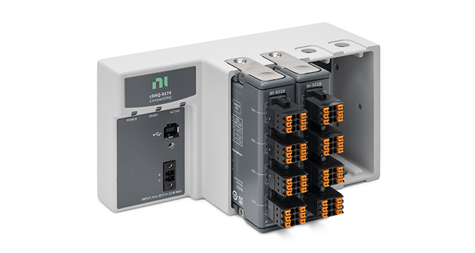
Simple Hardware Setup
Pair Your Strain Gage with Recommended Hardware
The NI CompactDAQ Strain and Load Measurement Bundle simplifies connecting your strain gage sensor with a bundle of strain/bridge input module(s) and a NI CompactDAQ chassis.

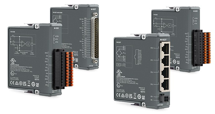
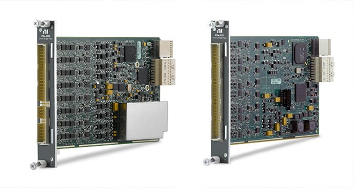
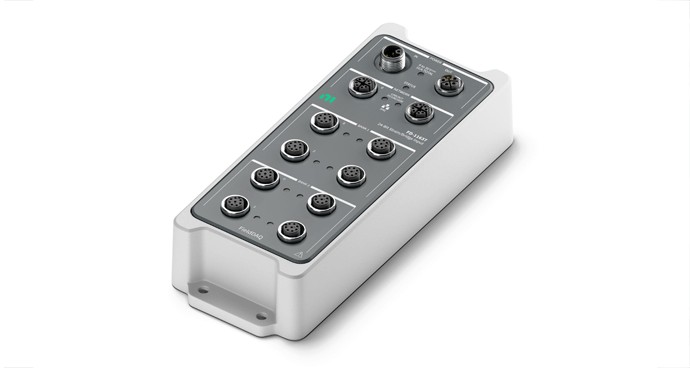
Other Products for Measuring Strain
The following products interface with strain gage sensors. These products can also take pressure, force, and torque measurements. Learn more about measuring pressure with bridge-based or other pressure sensors, load with bridge-based sensors, and torque with bridge-based sensor to choose the right sensors for use with NI products.