
Test Propels the Next Generation of Quiet, Speedy Aircraft
Test and measurement are the key to aircraft noise reduction to unlock aviation innovation benefits for companies, passengers, workers, and communities.
We all have struggles and challenges within our team or organization—whether it’s the junior engineer that couldn’t possibly be wrong about anything, ever; the dreaded consensus-building meetings that do anything but; or the nearly impossible deadline. Aerospace test engineers are no exception. They may be supporting depot-level test systems with 30-year old technology or racing to be first to market with the latest and greatest radar technology—whatever the case, there is no shortage of challenges to tackle.
The first, and most obvious, challenge that a test engineer may face is supporting legacy Test Program Sets (TPSs). Commercial and military aerospace programs are extending well beyond their intended lifecycles, and support teams must carry these fleets forward into the next wave of technology. When looking to upgrade a test system (or subsystem) for one of these programs, you must consider more than the technology insertion—you also must consider the hundreds or thousands of TPSs developed for the system and the ripple effect that technology insertion will inevitably have on the program as a whole.
The most motivating and technologically savvy approach involves developing a completely new test system with exciting new instruments, instrumentation test adapters (ITAs), and fixtures, while rehosting as many legacy TPSs as possible. Unfortunately, though, you ultimately have to answer to a budget and usually end up refurbishing existing test systems to replace the obsolete pieces through planned maintenance.
Take the example of refurbishing an existing system by replacing an obsolete oscilloscope with the objective of minimizing TPS migration costs. Sounds simple, right? On the surface, the test engineer’s job seems relatively straightforward: Find an oscilloscope that can perform as well (if not better) than the existing scope. After all, most scopes of today are going to run circles around the dinosaurs designed into the system 10 or 20 years ago.
But we encounter our first bump in the road with form factor. The new instrument needs to fit seamlessly into the 19” rack so as not to warrant a rack layout reconfiguration. Changing the rack layout introduces a massive cascade of system-level documentation changes (not to mention the possible signal integrity issues with changing cable lengths to the mass interconnect). This form-factor challenge is one of the many reasons that modular platforms like PXI (and formerly VXI) have dominated the aerospace/defense ATE market for the last 30 years. By following strict PXI specifications, you can find a scope from Vendor A that is the same size and utilizes the same backplane power as Vendor B—an easy system upgrade.
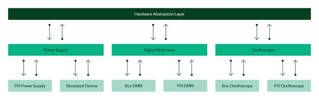
The second hurdle is hardware abstraction layer (HAL) integration. Any test system that is expected to last for at least five to ten years will inevitably have planned maintenance and operational costs. These are significantly reduced by abstracting vendor-specific hardware and drivers into a HAL or measurement abstraction layer (MAL). Test engineers also must evaluate the new instrument driver stack to ensure that they plug into the HAL—mitigating the risk when migrating the thousands of TPSs still to come. Many HALs utilize the IVI driver class where possible and supplement with plug-and-play drivers. Since this example is an oscilloscope, we’ll make an assumption that the test engineer has it “easy” and gets a pass on software, because there is an existing IVI class specified for oscilloscopes.
Figure 1: Hardware Abstraction Layers (HALs) significantly mitigate the impact of hardware obsolescence, but are difficult to justify in the absence of a long-term support strategy.
Thirdly, we examine the often-hidden answer to the question, “Is newer really better?” This new oscilloscope’s specifications are multiple generations ahead of the obsolete equipment, so where’s the issue? Well, for example, when you insert this new oscilloscope into the system and the rise time or settling time measurements change significantly because you’re sampling at three, five, or ten times the rate of the previous instrument, that generates dozens of incompatible TPSs that previously provided great system utilization. Another issue arises when legacy TPSs require trigger functionality that instrument vendors obsoleted years or decades prior. In this situation, the test engineer must search the entire database to identify which TPSs will be broken by inserting a new instrument that does not support the legacy trigger functionality—and sometimes, these databases don’t exist and require weeks or months of manual effort to compile.
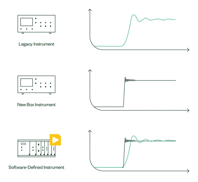
In order to minimize the unknown risks of TPS rehosting, many test engineers are taking advantage of software-designed instruments (SDIs) for more flexibility in the rehosting process. Software-designed (also known as synthetic) instruments combine core analog and digital front-end technology with powerful, user-programmable FPGAs to provide the most flexible instruments on the market. If we apply the SDI approach to the oscilloscope challenges above, we easily can implement custom trigger functionality on the FPGA of the SDI to emulate legacy-trigger technology. Some test engineers go further and use digital signal processing to emulate the analog performance of the legacy instrument’s analog-to-digital converter technology.
Figure 2: While difficult to accomplish, emulating legacy instrument capabilities greatly reduces the risk of TPS migration issues. Software-designed, or synthetic, instruments offer a unique approach to test equipment emulation.
On the other side of the spectrum (literally and figuratively) is the need to keep pace with the evolution of RF technologies engineered into radars, signal intelligence systems, communications equipment, and other line-replaceable units (LRUs). The rapid pace of innovation keeps test engineers on their toes in terms of building scalable architectures that not only can test the technologies of today, but scale to support the next wave of RF capabilities.
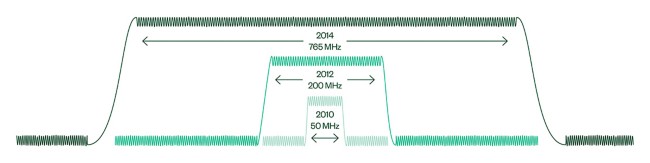
Figure 3: The evolution of NI vector signal analyzer bandwidth is one example of how aerospace ATE systems can scale to support the latest radar, communications, and signal intelligence systems.
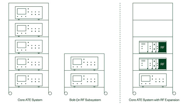
Historically, most high-mix test systems in aerospace/defense haven’t included RF ATE subsystems as part of the core configuration because of the cost/benefit analysis of adding high-performance (high-price) RF test equipment to cover a small set of LRUs. The asset utilization simply couldn’t justify the expense. As the number of RF-capable LRUs increases and RF instrumentation becomes more cost effective, it’s becoming more common for RF equipment to be part of core high-mix test system configurations.
Figure 4: Traditional ATE systems commonly used the bolt-on RF subsystem strategy because of the cost of RF equipment. As RF technology becomes more prevalent in LRUs and RF test equipment costs come down, we’ll see RF test equipment integrated into the core system.
To illustrate the complexity facing the test engineer, let’s examine a test system for a direction-finding, multiantenna radar subsystem. In the manufacturing environment, it’s reasonable to assume that each antenna will be tested serially using a high-performance signal source and a wide-band vector signal analyzer, along with some high-speed serial communication for controlling the UUT. Saying this is easy would be a massive overgeneralization, but when you compare this to the capabilities of the maintenance test system, it sounds simple. So, whose job is it to develop that complex test system for planned maintenance and field defective units? Our test engineer.
When performing maintenance tests or analyzing a returned unit from the field, your test cases are far more inclusive than the “did-we-build-it-right” manufacturing test case. You need to emulate the real-world environment with highly synchronized signal sources, including closed-loop control between the sources and analyzers to stress the DSP engine and measure the phase-coherency of the system. To address the synchronization and data transfer challenges, you need to look beyond traditional boxed instrumentation to a platform-based approach such as PXI. To emulate the real-world environment with closed-loop control, engineers need flexible RF instrumentation architecture that combines data streaming architectures, FPGA-based signal processing, and high-performance, high-instantaneous bandwidth RF front-end technology to capture and process the incoming pulses.
It’s also no secret that operational costs are high when sending units back to the intermediate- (I-) or depot- (D-) level centers for maintenance or repair. As RF test equipment becomes easier to adopt in field test, these operational costs greatly improve. Not only does the organization benefit from the decrease in operational cost, but they can get better IP leverage between the depot and field testers for in-situ troubleshooting and diagnostics.
As you can imagine, the RF challenges of scalability, synchronization, and latency create complex system-level test architectures for the test engineer and are quite different than replacing the legacy oscilloscope and mitigating TPS rehosting costs, though both technology elements are great opportunities for the test engineer to provide significant value to the organization.
Another more subtle pain point for test engineers is justifying short-term spend to mitigate long-term operational costs. Because market pressures are as high as they have ever been, test engineers often opt for point-solutions that neither provide the scalability for evolving technology demands nor have an architecture that simplifies maintenance for future upgradeability.
Furthermore, this short-term spend may not actually come directly from the test engineering budget. Looking upstream, we know how difficult it can be to get a design engineer to modify a design once it meets the design specifications, but organizations can see significant improvements to their bottom line by engaging the test engineering group early as part of a design for test (DFT) or design for manufacturability (DFM) strategy. When yields improve and asset utilization increases, these optimizations typically go directly to the product’s gross margin.
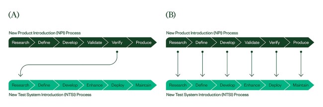
Beyond DFM, it’s critical that test engineers be involved early in the new product introduction (NPI) process. By actively engaging in every stage-gate of NPI, the test engineer can be developing product-specific test code along the way and collaborating with validation engineers on automated code modules to simplify validation and ease the transition into production. NI went through this process in the early 2000s, as we released more than 200 products a year with increased complexity per generation. By bringing test engineering to the conversation early, we saw over 40 percent reduction in release to manufacturing (RTM) time, which sped our time to market.
Figure 5: There are inefficient and costly flaws with the traditional approach of engaging test engineering late in the NPI process. Engaging earlier in the design cycle can lead to faster time to market, lower manufacturing cost, and improved yield.
If we look downstream, the test engineering budgets and the operations budgets are often decoupled, so the test engineering organization is not inherently incentivized to architect the system in a way that minimizes long-term operational costs. This is where siloed organizations struggle and strong communicators differentiate. At the heart of these negotiations and tradeoffs is the test engineer’s inherent knowledge of the suite of UUTs supported, the test system’s stability, and in which areas to optimize or improve. While it can be a growth opportunity for the test engineer, expanding their sphere of influence to encompass the entire design cycle makes them a truly valuable asset to the organization.
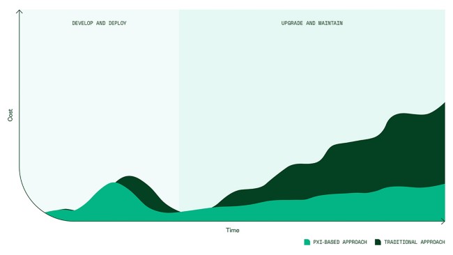
Figure 6: Many organizations have different business units for the develop/deploy and the support/maintain costs of a test system. Test engineers greatly can impact the operational costs of supporting a system, but must expand their influence beyond their own organization to understand and implement solutions to mitigate the long-term costs of supporting an ATE system.
While the challenges of obsolescence management, rapidly evolving RF requirements, and influencing DFM are by no means all-encompassing, they represent tremendous opportunity for the test engineer to impact the organization’s bottom line and showcase the value the test engineering team can deliver.
This article was originally published in High Frequency Electronics.