From Friday, April 19th (11:00 PM CDT) through Saturday, April 20th (2:00 PM CDT), 2024, ni.com will undergo system upgrades that may result in temporary service interruption.
We appreciate your patience as we improve our online experience.
From Friday, April 19th (11:00 PM CDT) through Saturday, April 20th (2:00 PM CDT), 2024, ni.com will undergo system upgrades that may result in temporary service interruption.
We appreciate your patience as we improve our online experience.
Time Sensitive Networking (TSN) is the evolution of standard Ethernet, specifically the IEEE 802.1 standard, to add capabilities such as time synchronization over the network and deterministic, low-latency communication to the open network of Ethernet. TSN synchronization is provided through the IEEE 802.1AS standard, which allows automatic synchronization between compliant Ethernet switches and end stations. This simplifies the way you synchronize your distributed measurement system, because you need only a single Ethernet cable between devices. The cable not only carries all your typical network packets, such as your measurement data, but also provides a common notion of time to which all devices in the IEEE 802.1AS subnet synchronize.
This synchronization technology was introduced to NI-DAQmx 17.1 with the release of the CompactDAQ Ethernet chassis with TSN, providing a simple way to synchronize your distributed measurement system over the network. Because all devices on the IEEE 802.1AS subnet have a shared notion of time, you can use time-based triggers and timestamps to achieve synchronization and correlation across networked systems for the first time in NI-DAQmx. Using time as a synchronization method provides a simple approach to correlating data from multiple devices with a known amount of uncertainty. This white paper walks through factors that can impact the overall synchronization accuracy, discusses the methods NI used to determine the network accuracy for its NI-DAQmx-based TSN devices, and shows you how you can characterize your own measurement system’s accuracy.
When designing and implementing a TSN distributed measurement system, you should consider a few factors that can impact network synchronization accuracy. These include the topology chosen for the distributed application, the quality of the IEEE 802.1AS grand master (GM) clock selected in the IEEE 802.1AS subnet, and the timing architectures of the I/O channels used within the synchronized application.
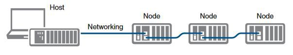
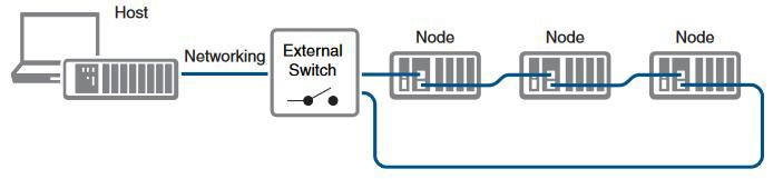
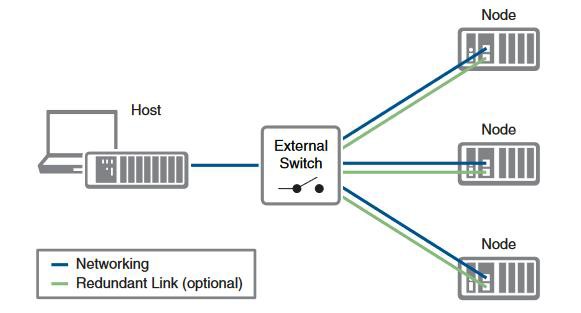
Synchronized distributed measurement systems are typically made up of multiple nodes. How these nodes are connected depends on which topology you use. The three basic topologies for synchronized distributed measurement systems are line, ring, and star.
Image 1: Line Topology
Image 2: Ring Topology
Image 3: Star Topology
When using TSN to synchronize the devices on the network, a common notion of time is distributed between all the devices in a given topology. As the number of devices increase in a line within the topologies, the number of bridges participating in synchronization increases. Each bridge adds tens of nanoseconds of uncertainty into the synchronization accuracy.
Learn more about designing NI-DAQmx-based Measurement Systems
Because clocks cannot be shared directly over the network, TSN-based devices synchronize by measuring and adjusting the relationship between their clock and a reference clock on the network. In the IEEE 802.1AS specification, the reference clock, referred to as the grand master (GM) clock, is selected automatically through an election algorithm. The election is based on clock quality, traceability, and priority; if there happens to still be a tie after those are announced, then it comes down to the MAC address of the device.
The GM clock has a stability specification that may include phase noise and/or Allan deviation. All other TSN devices in the subnet have a similar specification and also frequently adjust their clock to follow the GM clock, introducing additional low-frequency phase noise.
Learn more about the impact of the GM clock and how to achieve high-accuracy measurements with NI-DAQmx-based TSN devices.
To offer a broad range of high-quality measurements, C Series modules and FieldDAQ devices are supported using different types of timing architectures that are separated into two main groups: sample clock timed and oversample clock timed. Mixing these modules can have an impact on synchronization accuracy.
Sample clock-timed modules operate from a sample clock generated by a timing engine on the chassis. Based on the design, these clocks are phase aligned with the rest of the TSN subnet. The timing of the acquisition or generation operation is determined by digital delays in the timing engine and on the module itself.
Scanned modules are types of sample clocked-timed modules that contain a single analog-to-digital converter (ADC) for all channels. Scanned modules add per-channel delays as the single ADC must operate separately for each channel being acquired. When synchronizing scanned modules with nonscanned modules, care must be taken to associate samples from the scanned module and other module types.
Oversample clock-timed modules operate from high-precision clocks that run constantly. On the cDAQ-9185/9189 Ethernet chassis with TSN, these clocks are generated on the chassis itself and tuned to match other chassis clocks but are not phase aligned. These clocks do not drift from each other but could be misaligned by up to a half of a sample period between chassis. Because the clocks run constantly, another signal is required to synchronize the data from these clocks, the sync pulse. This signal indicates when the module should start producing or consuming data. Without this signal, the clock would be synchronized to the network but not the data. NI-DAQmx-based TSN devices can use time as the sync pulse to simplify distributed system development.
Learn more about how to achieve highly accurate measurements from NI-DAQmx-based TSN devices.
Learn more about synchronizing analog input C Series modules with NI-DAQmx.
For NI-DAQmx-based TSN hardware devices, within the device specifications under the section Timing and Synchronization, there are specifications for "Network synchronization accuracy." This informs you of the given synchronization accuracy in a configuration with mixed timing architectures and the topology selection, which increases the number of hops in a system. In some cases, NI also provides a specification that shows the level of synchronization accuracy you can achieve when you use an optimized configuration with identical modules and a low number of hops in the system.
The next couple of paragraphs walk through two examples that show setups used when benchmarking these specifications, using the 8-slot cDAQ-9189 chassis.
This test example took the uncertainty from different factors such as a selection of modules consisting of a variety of timing architectures and ensuring the configuration consisted of multiple hops in a line topology. The system consisted of six cDAQ-9189 chassis in a line topology networked to a single host PC. This meant that the GM of the IEEE 802.1AS subnet that was selected was one of the 8-slot cDAQ-9189 Ethernet chassis because all chassis were of identical clock quality, traceability, and priority; thus, the GM was determined by the chassis with the highest MAC address. The configuration was set up so that the GM was located at one of the ends of the chain to ensure the topology had the maximum amount of bridges participating in synchronization. When synchronizing devices with IEEE 802.1AS, the IEEE 802.1AS protocol compensates for the cable length between devices, so it was not necessary to ensure that the Ethernet cable lengths matched. A variety of SAR- and DSA-based modules were included in the six chassis. A known external waveform was then generated and sent into all the analog input channels on the modules. The waveforms were then taken from the analog input channels and signal processing was performed to determine the maximum phase offset seen in the system between all the analog input channels. All the synchronization performance numbers were based off of empirical results and represented typical behavior.
This test example removed all possible uncertainty to develop an optimized configuration. The system consisted of two cDAQ-9189 chassis in a line topology networked to a single host PC. Because this depended on the MAC address of the two chassis connected, the one with the highest MAC address became the GM of the IEEE 802.1AS subnet. With just two chassis connected, this system consisted of only a single hop to reach all devices on the subnet. This is similar to a star topology behavior. As in the previous example, the Ethernet cable length between the two devices—as long as it was within the Ethernet specification—did not matter because the IEEE 802.1AS protocol compensates for the cable lengths between devices. To eliminate all possible uncertainty, identical modules were used in the two chassis for this test, which enabled the system to consist of only one type of timing architecture. A known external waveform was then generated and sent into all the analog input channels on the modules. Waveforms were then taken from the analog input channels and signal processing was performed to determine the maximum phase offset seen in the system between all the analog input channels. All the synchronization performance numbers were based off of empirical results and represented typical behavior.
When designing a TSN synchronized measurement system, it is always best practice to characterize the typical synchronization accuracy you will achieve, so you have that uncertainty information when performing any post-processing on the data. Although NI provides synchronization accuracy specifications for the typical behavior of a system in two different configurations, these represent typical behavior of the devices, and I/O synchronization accuracy is system-dependent. To characterize the performance of a measurement system, acquire or generate a known signal and test the results for expected properties. For analog input synchronization, acquire a sine wave of known frequency at several channels on different chassis and extract the acquired signal’s phase and frequency. Errors in frequency reflect the difference in frequency between the GM oscillator and the clock generating the known signal. In a synchronized measurement system, this error is consistent at all points. Errors in phase reflect temporary phase differences between the clocks on different devices and differences in the I/O module signal paths. For identical modules, phase errors should scale with the number of hops between devices in the measurement system.
Learn more about achieving highly accurate measurements with NI-DAQmx-based TSN devices.