From Friday, April 19th (11:00 PM CDT) through Saturday, April 20th (2:00 PM CDT), 2024, ni.com will undergo system upgrades that may result in temporary service interruption.
We appreciate your patience as we improve our online experience.
From Friday, April 19th (11:00 PM CDT) through Saturday, April 20th (2:00 PM CDT), 2024, ni.com will undergo system upgrades that may result in temporary service interruption.
We appreciate your patience as we improve our online experience.
Programmable DC power supplies are essential tools that can source power to a connected device. When sourcing, the power is generated in the supply and dissipated in a device under test (DUT); when sinking, the DUT generates power and it dissipates in the supply. When choosing a programmable power supply, it’s important to understand some of the features that are available to you, such as constant voltage mode, constant current mode, remote sense, and isolation. Let’s talk about why these features matter and also how you can incorporate them into your test and measurement system.
Commonly used in research, design, development, and production applications, a DC power supply is an instrument that can source DC power to a connected device. A device connected to a power supply can be referred to as a load, device under test (DUT), or unit under test (UUT), depending on the context. To characterize a DUT or test if a DUT is working as expected, many DC power supplies have the ability to simultaneously source power and measure the voltage or current consumed by the DUT. Typically, power supplies provide a constant current or constant voltage and monitor the resulting voltage drop or current draw. A programmable DC power supply can be automated using a computer to communicate with the device. Some programmable DC power supplies can store output sequences or measurements in onboard memory, while others can handle only immediate actions.
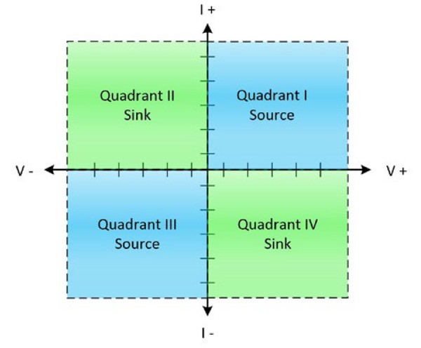
Figure 1. Most DC power supplies operate in quadrant I, providing positive voltage and positive current, or quadrant III, providing negative voltage and negative current.
Referring to the I-V diagram in Figure 1, most DC power supplies operate in Quadrant I, providing positive voltage and positive current, or Quadrant III, providing negative voltage and negative current. The formula to calculate DC power is P = V x I. In Quadrant I, voltage and current are both positive; in Quadrant III, voltage and current are both negative. In both cases, plugging the numbers into the power formula results in a positive power output, which is called sourcing. Operating in Quadrant II and IV results in a negative power output, which is called sinking. When sourcing, the power is generated in the supply and dissipates in the DUT. When sinking, the power is generated in the DUT and dissipates in the supply.
Some devices called source measure units (SMUs) can operate in all four quadrants, sourcing and sinking power. You can think of an SMU as an ideal rechargeable battery. When you connect the battery to the charger, the battery draws, or sinks, power from the charger. Then when you disconnect the battery from the charger and use it to power a flashlight, the battery becomes a source that provides power for the light bulb. SMUs are commonly used to characterize batteries, solar cells, power supplies, DC-DC converters, or other power-generating devices.
Another differentiating factor between a DC power supply and an SMU is precision. Some applications are especially demanding and require higher precision than a typical power supply offers. It is common for SMUs to have high precision in the µV or pA range, which is why they are often preferred when the accuracies of sourced and measured values are important and the application requires sensitivity beyond that of a typical power supply. If precision is critical to your application, learn more in our Analog Sample Quality: Accuracy, Sensitivity, Precision, and Noise white paper.
In addition to understanding the differences between sourcing and sinking power, it is also important for you to understand the difference between constant voltage mode and constant current mode. Programmable DC power supplies can operate in either constant voltage mode or constant current mode, depending on your desired output levels and load conditions.
In constant voltage mode, which is sometimes referred to as voltage-controlled mode, a power supply behaves like a voltage source, holding the voltage across the output terminals constant while the current output varies, depending on load conditions. If your load resistance changes, Ohm’s law (V = I x R) dictates that the supplied current must also change proportionally to maintain the power supply output voltage level. If a DUT’s resistance suddenly drops, then the power supply increases the current to hold the voltage constant.
When using a programmable DC power supply, you can set the desired current limit. If your load attempts to draw more current than the programmed current limit allows, then the power supply begins to operate in compliance, meaning that the power supply is unable reach the requested output voltage level without violating the user-programmed current limit in place. At this time, the power supply switches to constant current mode and the current is held at the current limit. This pivotal load resistance level is referred to as the compliance resistance, which can be calculated by dividing the voltage setpoint by the current limit. Other common names for compliance resistance are critical resistance and crossover resistance.
For example, suppose you want to supply a constant 5 V (VS = 5 V) to your DUT, which typically provides a 50 Ω load resistance (RL = 50 Ω). Additionally, you decide to limit the current output to 300 mA (IS = 0.3 A) to prevent damage to the DUT. Using the compliance resistance formula (RC = VS / IS), you calculate that 16.67 Ω is the minimum load resistance to keep the output operating in constant voltage mode. If your load resistance fluctuates, but stays above 16.67 Ω, then your power supply continues to provide a constant 5 V. If the DUT fails, dropping the load resistance below 16.67 Ω, then the power supply begins to operate in compliance, switching to constant current mode and outputting a steady 300 mA at a voltage level less than 5 V.
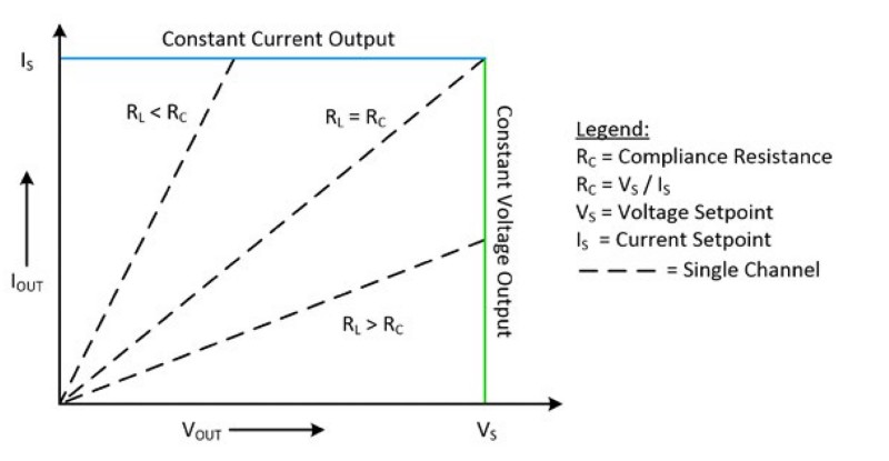
Figure 2. When outputting a constant voltage, you can set a current limit to protect the DUT
Constant current mode is essentially the opposite of constant voltage mode. In constant current mode, also known as current-controlled mode, the power supply behaves like a current source, holding the current flowing through the output terminals constant while the output voltage varies depending on load conditions. Referencing Ohm’s law, if your load resistance changes, then the voltage must also change appropriately to maintain a constant current. If the DUT from the previous example fails and causes the load resistance to drop, then the power supply decreases the output voltage proportionally to hold the current constant. For example, constant current operation is desirable when controlling LEDs that can be damaged by high current.
Constant current mode is also limited by a configurable voltage limit, imposing a compliance resistance similar to constant voltage mode. You can use the same calculation used in the Constant Voltage Mode section to calculate your compliance resistance for constant current operations. However, for constant current mode, your load resistance must stay below the compliance resistance to maintain the desired constant current. Figure 2 illustrates the compliance resistance concept for both constant voltage and constant current mode.
A unique application that requires both constant voltage and constant current operation is charging a Lithium-Ion battery, which is a common type of rechargeable battery that is used in portable electronics because of its energy density, lack of memory effect, and slow loss of charge when not in use. To recharge a Lithium-Ion battery, the power supply should apply a constant current, monitoring the battery voltage level until the battery reaches its maximum voltage. After the Lithium-Ion battery is fully charged, the power supply should switch to constant voltage mode, which provides the minimum current required to hold the battery at its maximum voltage.
A key feature on most programmable DC power supplies is the ability to measure the generated current and voltage. This feature is essential for many applications such as I-V curve tracing, where current draw must be measured for multiple voltage setpoints. The measurement operation of a programmable DC power supply is similar to the measurement capabilities of a digital multimeter (DMM). As with any measurement device, there is a trade-off between the speed at which you perform measurements and the amount of noise in those measurements.
To make these measurements, choose a programmable power supply with a measurement method that works for your environment. For example, NI offers NI-DCPower, with APIs for many common programming languages, as well as InstrumentStudio, which you can use for easy and efficient interactive measurements.
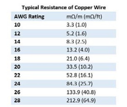
A challenge in accurately sourcing or measuring precise voltages is the effect that lead resistance has on the voltage that a DUT sees. Lead resistance is always present but can become problematic when using very long, small-gauge wires. Table 1 provides the typical resistances of different gauges of copper wire. Although typically no larger than a few ohms, these small resistances can have a large affect on the voltage a DUT receives, especially when the internal resistance of the DUT is small.
Table 1. Lead resistance from wire can have a large affect on the voltage a DUT receives.
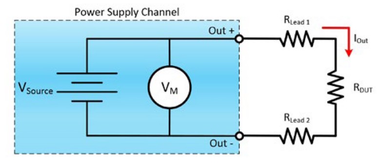
Figure 3 shows a diagram of a generic circuit that consists of a power sourcing instrument, lead wires,connecting the power source to the DUT. In this case, the leads are 24-foot-long 26 AWG copper wires, with a resulting lead resistance of approximately 1 Ω for both the positive and negative lead wires connecting the power source to the DUT. The current coming out of the power supply causes a voltage drop across Rlead1 and Rlead2, resulting in the voltage across RDUT being less than Vsource.
Figure 3. This shows an example connection diagram for a typical programmable DC power supply that can be used to calculate the voltage a DUT receives.
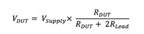
Assuming that the power source is set to an output of 5 V and the DUT has an impedance of 1 kΩ, you can calculate the actual voltage seen at the terminals of the DUT using the following equation.
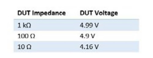
For the initial case, the voltage seen is actually just 4.99 V. For some devices, this small change is not an issue; however, for applications that require precise characterization based on operating voltage, this error can become critical. Furthermore, for devices that have lower input impedances and therefore draw a lot of current, the actual voltage at the DUT can be substantially lower than the voltage at the output of the power supply. Table 2 lists the values that the example DUT sees based on lower values of its input impedance.
Table 2. For devices with lower input impedances, the voltage observed at the DUT can be substantially lower than the voltage at the output of the power supply because of lead resistance.
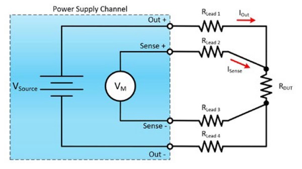
The solution to lead-resistance-induced voltage error is remote sensing, also known as 4-wire sensing. This technique accounts for the voltage drop across the lead resistance by measuring the voltage directly at the DUT and compensating accordingly. This method is similar to the way that DMMs perform 4-wire resistance measurements to remove the effect of lead resistance from resistance measurements. Most power supplies, SMUs, and DMMs feature two extra terminals on the output to allow for this 4-wire remote sensing technique, and these extra terminals are connected directly at the DUT, as shown in Figure 4. Although there is still lead resistance in the wires used for remote sensing, voltage measurements are high-impedance so no current flows through the sense wires and no voltage drop is seen.
Figure 4. Remote sense is a 4-wire connection technique that can eliminate the effects of lead resistance.
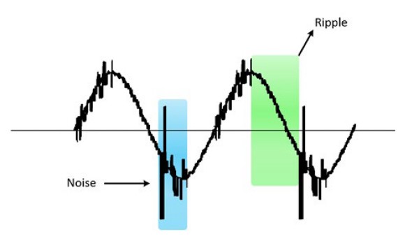
When considering which programmable DC power supply to use in your application, it is important to consider output ripple and noise, which is sometimes referred to as Periodic and Random Deviation (PARD). True noise is random and spread across all frequencies when viewed in the frequency domain, whereas ripple is typically periodic. Ripple is introduced by the AC-to-DC rectification required to convert the AC power from the wall outlet to the desired DC levels. Depending on the type of regulation used by a power supply, ripple has either one or two fundamental frequencies.
DC power supplies typically use either linear or switching regulation to convert the 50/60 Hz AC power source to a DC power signal. Linear regulation power supplies use an AC-to-DC transformer to convert the line voltage to a stable DC output. Therefore, the voltage output of a linear regulated power supply generally has a 50/60 Hz low-frequency ripple in addition to any extra noise present. Linear regulated power supplies typically have low ripple and noise, but they also have low efficiency, large size, and produce more heat. On the other hand, switching power supplies convert the 50/60 Hz current to a much higher frequency, resulting in some periodic, high-frequency ripple in addition to the 50/60 Hz low-frequency ripple. Switching power supplies are typically more compact, produce less heat, and are more efficient, but they are very susceptible to high-frequency noise. Figure 5 shows an illustration of a high-frequency ripple and random noise.
Figure 5. In power supplies, noise typically is random and spread across all frequencies, where as a ripple is periodic.
Additionally, transmissions from programmable DC power supplies can be affected by environmental noise, which adds to any inherent system noise. To reduce the effects of environmental noise, it is important to use shielded, twisted pair wires when possible.
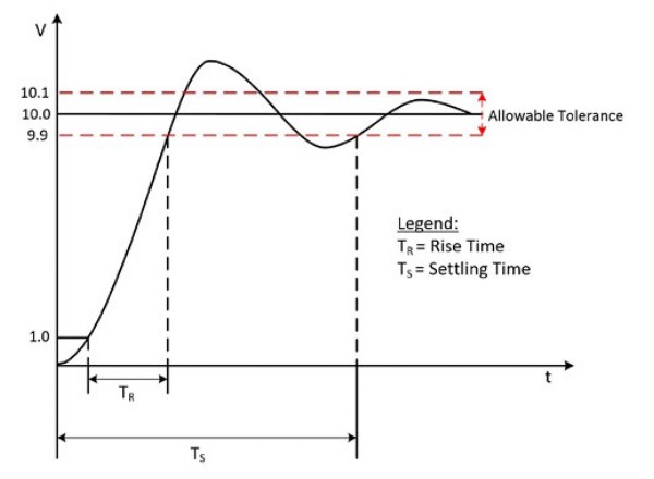
Rise time and settling time are key indicators of a power supply’s ability to reach the desired voltage level and stabilize. Specifically, rise time is the amount of time required for the output to transition from 10 percent to 90 percent of the configured output. Settling time describes the amount of time it takes for an output channel to stabilize within a specified percentage of its final value, including the rise time.
Figure 6 illustrates both rise time and settling time for a power supply output changing from 0 V to 10 V.
Figure 6. Rise time and settling time are key indicators of a power supply’s ability to reach the desired voltage level and stabilize.
Rise time and settling time are important power supply specifications because they can directly affect measurement time, requiring extra time to wait for the circuit to recover from the transient before you can take the next measurement. Measurement time is especially important for situations, such as in automated test systems, where reducing measurement time can also reduce your overall cost.
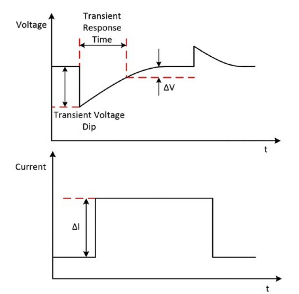
A transient response typically describes the response of a system to a change from equilibrium. For a DC power supply, transient response describes how a power supply operating in constant voltage mode responds to a sudden change in load current. Changes in load current, such as a current pulse, can cause large voltage transients as shown in Figure 7. As the power supply’s internal control circuit compensates for the change in load current, the voltage settles back at the desired level. The transient response of a power supply specifies how long it takes for the transients to recover within a certain percentage of the voltage setting. Typically, the transient response is specified as the amount of time required to recover to a percentage of the voltage setpoint after a 50 percent change in load current. For example, a device might be capable of recovering to 0.1 percent of the original voltage setpoint within 50 µs after a 50 percent change in load current.
Figure 7. Transient Response to a Current Pulse
Considering an application, if your DUT resistance suddenly drops causing a current pulse to occur, then a transient voltage dip occurs before the power supply’s internal control circuit can compensate for the change in load. Similar to rise time and settling time, the transient response specification of a power supply is important because it can impact measurement time. For more information about transient response and load considerations, see the Power Supply Line and Load Regulation and Cascading Considerations white paper.
Isolation is a means of physically and electrically separating two parts of a measurement or sourcing device. Electrical isolation pertains to eliminating ground paths between two electrical systems. By providing electrical isolation, you can break ground loops, increase the commonmode range of the power supply, and level shift the signal ground reference to a single system ground. Power supply isolation specifications are particularly important if you are considering cascading the outputs of a power supply to extend the voltage and current ranges, which is covered in greater detail in the Power Supply Line and Load Regulation and Cascading Considerations white paper.
The most robust isolation topology is channel-to-channel isolation. In this topology, each channel is individually isolated from one another and from other non-isolated system components. In addition, each channel has its own isolated power supply.
NI offers programmable power supplies for both rack-mount and PXI Express systems that can do all of the things that we’ve talked about in the previous sections.
The PXI Programmable Power Supply provides up to 120 W of power in a single PXI slot, which saves expensive rack space within the test system. The fully programmable power supplies have output disconnect relays to isolate the instrument from the DUT, remote sense to correct for losses in system wiring, and integrated timing and synchronization through the PXI platform.
For higher output power requirements, choose NI’s Programmable Power Supply Device, which provides programmable DC power in either full or 1/6 rack-width, rack-mount form factor. The Programmable Power Supply Device is a single-channel, rack mount DC power supply. Certain models can source hundreds of watts in a compact design that makes it ideal for test systems that need multiple power rails.