Overcome the Challenges of Building High-Channel-Count, High Speed Measurement Systems
Overview
Many traditional high-speed oscilloscopes feature two to four channels and operate as stand-alone box instruments. While this is an effective solution for benchtop debugging, it’s often difficult to scale these instruments for high-channel-count applications such as beamforming and medical imaging, which require tens or hundreds of channels simultaneously sampling at high speeds. High-channel-count, high-speed DAQ systems must maximize channel density, synchronize multiple channels, and process massive amounts of data. Overcoming these challenges is much more practical with a modular platform that simplifies channel synchronization and enables high-throughput data streaming in a compact form factor. PCI eXtensions for Instrumentation (PXI) is ideal for building high-channel-count systems because it meets these traditional challenges and offers a history of reliability in a wide variety of applications. The PXI platform is built on the concept of virtual instrumentation, which uses software to define the functionality of instruments and helps you build measurement and automation systems that suit your needs exactly instead of limiting your options with traditional fixed-function instruments.
Contents
- Challenge 1: Maximize Channel Density
- Challenge 2: Synchronize Multiple Channels
- Challenge 3. Process Massive Amounts of Data
- Learn More
Challenge 1: Maximize Channel Density
When building a high-performance application with hundreds of channels, space quickly becomes an issue. The PXI platform offers a high-performance, low-cost deployment solution for measurement and automation systems in a compact form factor. A PXI system consists of a controller, a chassis, and various instruments such as oscilloscopes, digital multimeters (DMMs), and arbitrary waveform generators.
Traditional box instruments have their own dedicated processor, display, power supply, and fan for every two to four channels. PXI can maximize channel density by condensing these redundant components into a single chassis and controller, leaving only the analog and digital circuitry on the module. The space saved through this consolidation optimizes the amount of channels per module, so you can build systems with up to 544 channels in a single 4U rack space.
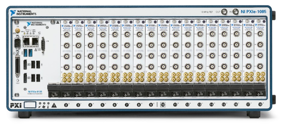
Figure 1. With the modular approach of the PXI platform, you can create high-density acquisition systems using a variety of high-speed or high-resolution modules.
Table 1 shows various oscilloscopes from high-bandwidth, high-speed modules such as the NI PXIe-5186 to extremely high-channel-count modules such as the NI 5752 adapter module for NI FlexRIO. The NI PXIe-5170R and NI PXIe-5171R combine the high performance of NI oscilloscope instruments with the user programmable FPGA of NI FlexRIO adapter modules in a single, 8-channel PXI module.
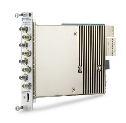
Figure 2. The NI PXIe-5171R delivers 8 high-performance channels in a single PXI slot.
Based on your bandwidth and resolution requirements, you can find an NI oscilloscope or digitizer that provides optimal channel density for your application.
| Module | Resolution | Sample Rate | Bandwidth | Channel Count per Module | Channel Count per Chassis |
| NI 5752 | 12 | 50 MS/s | 14 MHz | 32 | 544 |
| NI PXIe-5171R | 14 | 250 MS/s | 250 MHz | 8 | 136 |
| NI PXIe-5170R | 14 | 250 MS/s | 100 MHz | 4/8 | 68/136 |
| NI PXI-5105 | 12 | 60 MS/s | 60 MHz | 8 | 136 |
| NI PXIe-5160 | 10 | 2.5 GS/s | 500 MHz | 4 | 68 |
| NI PXIe-5162 | 10 | 5 GS/s | 1.5 GHz | 4 | 68 |
| NI 5772 | 12 | 1.6 GS/s | 2 GHz | 2 | 34 |
| NI PXIe-5186 | 8 | 12.5 GS/s | 5 GHz | 2 | 10 |
Table 1. NI oscilloscopes and digitizers offer optimal channel density for your applications.
Challenge 2: Synchronize Multiple Channels
The second major challenge of high-channel-count systems is ensuring that the data from each channel is synchronized. Synchronizing channels between multiple oscilloscopes is difficult if each instrument has its own timing and synchronization engine. Even when box oscilloscopes support multi-instrument synchronization, you must calibrate out any clock skew delays resulting from different cable lengths or types. Additionally, routing trigger lines and sample clocks between box instruments becomes progressively more cumbersome as channel count increases.
Timing and Synchronization
PXI overcomes many traditional synchronization challenges by using an integrated timing and synchronization architecture to route synchronization clocks and triggers internally. A PXI chassis incorporates a dedicated 10 MHz system reference clock, PXI trigger bus, star trigger bus, and slot-to-slot local bus, while a PXI Express chassis adds a 100 MHz differential system clock, differential signaling, and differential star triggers to address advanced timing and synchronization needs.
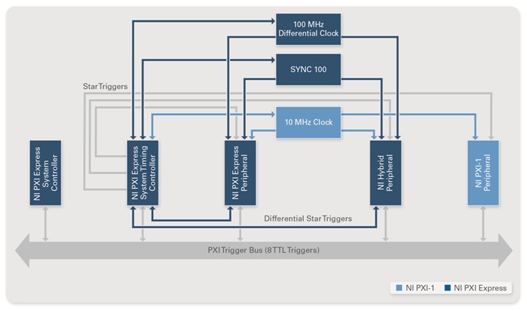
Figure 3. With the PXI timing and synchronization architecture, you can route trigger lines and reference clocks with minimal clock skew and drift.
NI Oscilloscopes Timing and Sync
In addition to the synchronization benefits of the PXI platform, NI designed its PXI oscilloscopes with other features that further simplify this process. From single-board channel expansion to the multichassis synchronization of instruments acquiring at different sample rates, NI PXI oscilloscopes offer the ideal hardware and software tools for synchronized high-speed DAQ.
NI has simplified the software tasks associated with building high-channel-count applications such as programmatically routing sample clocks and sharing triggers. Using powerful software tools such as NI LabVIEW, you can easily synchronize a few channels through channel expansion or hundreds of channels through the NI-TClk API. Channel expansion is a simple way to synchronize channels within a single digitizer and involves specifying your acquisition channels within a single resource string, as shown in Figure 4.
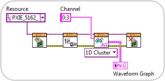
Figure 4. Single-Board Synchronization Through Channel Expansion
To synchronize over multiple instruments, NI has developed a patented method for synchronization called NI-TClk, which is designed to:
- Align the sample clocks that may not necessarily be aligned initially despite being phase locked to the 10 MHz reference clock
- Enable the accurate triggering of synchronized devices
The flexible NI-TClk technology is applicable to the following use cases:
- High-speed modular instrument synchronization with a sample clock or reference clock
- Extension of synchronization from a single PXI chassis to several PXI chassis to address high-channel systems using a system timing module
- Homogeneous and heterogeneous synchronization—devices running at the same or different sample rates using internal or external sample clocks
The NI-TClk API simplifies the user experience by helping you configure the trigger settings and clock synchronization through three LabVIEW functions (VIs) that make your system appear as one multichannel oscilloscope. The three LabVIEW VIs require no external parameters and work by simply passing an array of instrument sessions into the NI-TClk API. NI-TClk architectures can deliver synchronized devices with skews of at worst 1 ns between each device. Typical observed skews fall between 200 ps and 500 ps. Manual calibration of the sample clock on each device can lower skews to less than 30 ps between devices.
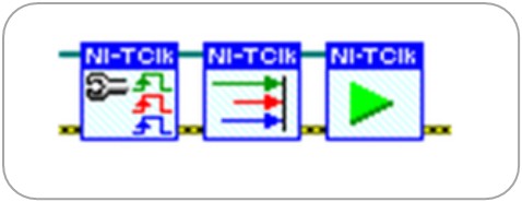
Figure 5. The NI-TClk API for Synchronizing Channels Over Multiple Instruments
Advanced Topic: Synchronizing PXI Oscilloscopes Over Multiple PXI Chassis
If you need additional channels or higher clock accuracy than the PXI chassis natively provides, the platform accepts multichassis synchronization and precision timing and synchronization modules with reference clocks capable of 50 parts per billion accuracy compared to the typical 100 parts per million accuracy of box oscilloscopes. If the required distance between synchronized chassis is too great for cables to reliably transmit clock and trigger signals, you can use a time-based synchronization architecture. With an NI PXI timing and synchronization solution, you can take advantage of absolute time reference protocols such as IEEE 1588, GPS, and IRIG-B to achieve synchronization over large distances.
Challenge 3. Process Massive Amounts of Data
One of the major bottlenecks of high-speed DAQ has traditionally been data storage and bus throughput back to the host. As instrument sampling rates increase, the streaming limitations of GPIB interfaces significantly reduce the performance of the digitizer. System throughput and onboard memory are especially important for high-channel-count applications because you rely on them when collecting data from tens or hundreds of channels and processing it on the same host. For example, a digitizer acquiring 8-bit data at 5 GS/s can generate 5 GB of data every second. Due to this massive amount of data, the oscilloscopes in your system need to incorporate deep onboard memory along with a high-bandwidth bus to stream data back to the host.
Figure 6 shows a performance comparison between various buses. By using the high-bandwidth PXI Express bus architectures, data can stream to and from the hard disk at a rate high enough to support high-end oscilloscopes.
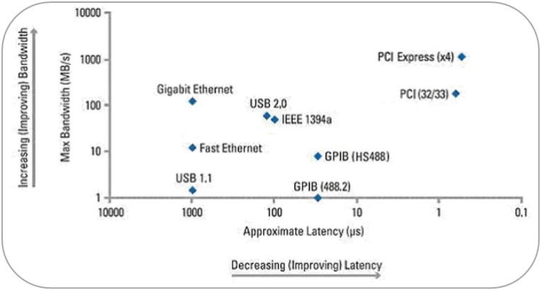
Figure 6. Bandwidth and Latency Comparison of Common Buses Used in Automated Test
Stream to Host
Streaming performance for PXI applications is based on the throughput rates for the system chassis, controller, and instrument. Evaluating each connection in a streaming architecture is important to maximize the overall system throughput. Using the latest in PXI Express technologies, the system bandwidth for NI chassis and controllers can support up to 12.8 GB/s, which is a dramatic improvement over the 8 MB/s throughput rate of GPIB. With bus, processor, and memory technology evolving so rapidly, the PXI platform gives you the flexibility to maintain a state-of-the-art test system.
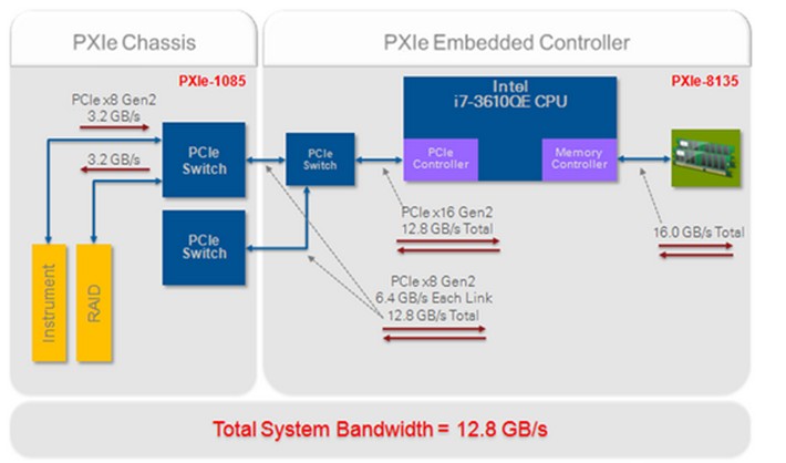
Figure 7. System Throughput Rates of the NI PXIe-1085 Chassis and NI PXIe-8135 Embedded Controller
Onboard Memory
Even with a high-performance bus, many applications still require deep onboard memory to temporarily store data and keep up with the full sampling rate of high-speed oscilloscopes. With deep onboard memory, the digitizer can sample at its maximum rate, store data locally, and then transfer the data to the host computer once acquisition is complete. Oscilloscopes with deep onboard memory can maintain their maximum sampling rates for longer periods of time, so their acquisition time windows are increased. NI PXI Express oscilloscopes such as the NI PXIe-5162, 5 GS/s oscilloscope, have 1 GB of available memory per channel to optimize acquisition time when running at full sample rates.
Advanced Streaming Through RAID
The PXI platform offers a cost-effective solution not only for data streaming but also for easily moving data between multiple test setups or supplementing the PXI system controller’s storage capacity with a redundant array of inexpensive disks (RAID). RAID is a general term for mass storage schemes that split or replicate data across multiple hard drives and can provide the necessary bandwidth and storage for high-channel-count applications. NI offers several data storage options based on external RAID hard drive enclosures and an in-chassis PXI module for control.
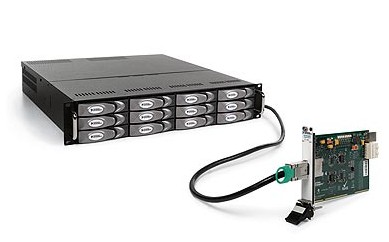
Figure 8. The NI HDD-8265 can stream up to 750 MB/s with an available 24 TB of storage.