Materials
The following is a list of materials and tools needed to create the sensor:
- 1 12-inch piece of phone wire, at least 4 wires wide
- 1 Photoresistor with peak sensitivity near 650 nm
- 1 Red LED, recommended brightness of 10,000 mcd or higher
- 1 Header with at least 4 pins
- Waterproof medical tape
- Double-sided tape
- Soldering Iron and Solder
- Heat-shrink
- Scissors
- Wire stripper/wire cutter
Assembly Instructions
-
Remove 3 inches of wire casing from each end of the phone wire to expose the wires inside. For the heart rate monitor, you will be using four wires to attach the LED and photoresistor. Trim two of the wires by 1.5 inches on the sensor end, as shown in Figure 1 below. Use the wire stripper to remove the casing from each of the four wires on both the sensor end and header end.
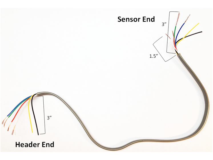
Figure 1: Wire prepared for attaching sensors
-
Slip a small piece of heat shrink over each on the header end of the phone wire. Next, solder each wire to a pin on the header and carefully shrink the heat shrink over each solder joint using a lighter or the heat of the soldering iron.
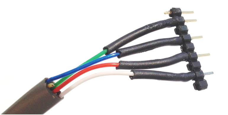
Figure 2: Header pins soldered to header end of sensor cable
-
As in Step Two, slip a piece of heat shrink over each of the wires on the sensor end of the phone wire. Solder the LED to the set of shorter wires, being careful to minimize the amount of heat placed on the LED wires to avoid damaging the light-emitting diode. Next, follow the same process to attach the photoresistor to the set of longer wires on the sensor end of the cable, again ensuring that you minimize the heat on the wires to prevent damage. Finally, shrink the heat shrink on all four wires using a heat source.
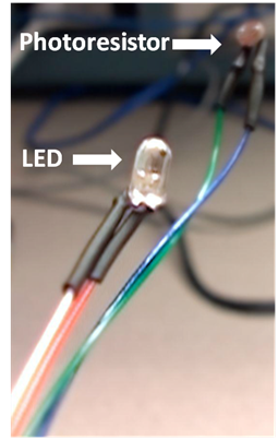
Figure 3: Photoresistor and LED
-
The next steps are designed to create the wrapping to keep the sensors in place around the test subject’s finger. First, we will lay the photoresistor and LED in line on a piece of medical tape about 5 inches long. Make sure to keep the tape sticky-side up; the wires should be stuck to the adhesive.
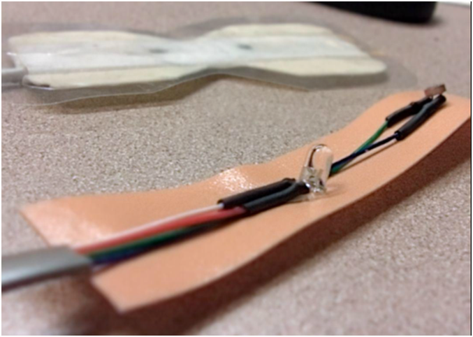
Figure 4: Sensor backing
-
Next, cover the exposed wires by trimming tape strips to fit around both the photoresistor and LED. The sticky side of the new tape strips should be face down. The end result will be the sensor base, with the two components enveloped between the tape with a smooth outer layer.
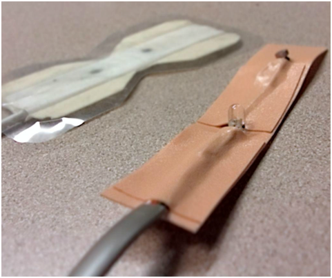
Figure 5: Cover exposed wires
- You have now created the base of your sensor. Next, you will create the replaceable wrapper that attaches the sensor to the subject’s finger, blocking out ambient light noise. Cut two pieces of tape the same length as the sensor base. Place the pieces of tape on your table, sticky side up. Gently place the sensor base on top of one tape strip so that it slightly overlaps, sticking the two together. Repeat for the second tape strip.
Figure 6: Preparing the covering
- Cut out notches on the side of the sensor to create flaps that fold over the subject’s thumb.
Figure 7: Cut notches for easy wrapping
- Using the double-sided tape, create cushions to place around the LED and the photoresistor. The goal of this cushion is to build up the area around the sensors to keep them as flat and stable as possible. It also helps to channel the light from the LED to the photoresistor.
Figure 8: Build padding to support the LED and Photoresistor
The sensor is now complete. To use the sensor, carefully align the LED and the photoresistor on either side of the patient's thumb, and wrap the tape around the thumb to block out light. If you are not receiving clear readings, make sure that the LED and the photoresistor are parallel to each other, and that they are aligned on opposite sides of the thumb.