From Friday, April 19th (11:00 PM CDT) through Saturday, April 20th (2:00 PM CDT), 2024, ni.com will undergo system upgrades that may result in temporary service interruption.
We appreciate your patience as we improve our online experience.
From Friday, April 19th (11:00 PM CDT) through Saturday, April 20th (2:00 PM CDT), 2024, ni.com will undergo system upgrades that may result in temporary service interruption.
We appreciate your patience as we improve our online experience.
Contact Information
Competition Year: 2016
University: University of Strathclyde
Team Members Andrew Fickling (2018):
Faculty Advisers: Voluntary Student Project
Email Address:andrew-fickling@outlook.com
Country: UK
Project Information
Title: Development of Vehicle Dynamics Model using Adams Car for Formula Student Race Car
Background
Formula Student is an international design competition where students will design, manufacture, develop, market and race a single seat racing car. At University of Strathclyde Motorsport we pride ourselves in being a completely student lead team now in our 16th year consistently competing at Formula Student UK and Formula Student Germany. Although a comparatively low budget team we still remain as one of the top team in the UK specialising in the static events winning the cost and sustainability event in 2014 and acheiving 3rd in 2015. However, to climb the ranks the team now has to focus more on the dynamic events and enhance our understanding of the car to implement more radical design changes.
Therefore the aim of the 2016 season was to act as a development year by ironing out the basic issues with the 2015 car but focussing on testing and validation of designs through data aquisition and analysis coupled with software model development to then be implemented into the 2017 car. In addition to this this validation season will lay foundations for future teams to validate and test their designs.
Figure 1 - USM15, Univerity of Strathclyde Motorsports 2015 Season Car at Formula Student Germany
Products
Compact RIO cRIO-9035
myRIO-1900
NI 9381 Module
NI 9853 CAN Module
NI 9795 Wireless Module
NI 9235 Strain Gauge Module
The Challenge
The aim of the project was to develop a data aquisition system which could be added and removed from the car easily with the capability of taking in a number of sensor readings logging onboard. The team has previously attempted data logging with the addition of a more permenant loom which added over 5kg of weight and so it would be prefferable to use the data logging and analysis system for testing only. However ease of management of the data is also critical to allow the team to take the data and be able analyse it easily for use in future car designs and validation of current designs. In addition to this a smaller data logger with wireless capabilites will allow certain parameters to be monitored track side while the car is running. The data will then be used to correlate with an Adams Car model from MSC which will simulate the exact dynamic behaviour of the car. Once calibrated this could then be used to make more dramatic changes to the cars design as opposed to the itterative design processes using Matlab and Excel models which have been previously adopted. 
Figure 2 - Example Excel Model simulating the loads on various suspension components in different load cases
The Solution
The data aquisition system consists of two seperate designs: a testing only data logging system consisting of a Compact RIO (cRIO-9035) system with various module inserts to enable communication with the CAN bus already installed on the car and external sensors which can be removed easily. The secondary system consists of a myRIO-1900 system which will be used during competitive events only to log vital components of interest and failure indicators. This will utilise an X-CAN module to communicate with the CAN bus to record these parameters over Wi-Fi in addition to driving the driver dash board interface.
Through a thorough testing phase the data collected will be analysed using DIAdem software to correlate the data from various sensors with each other and video footage and then used to alter setups at testing, validate designs and lay foundations for future designs. Although a myDAQ system would be more appropriate for this particular application the Compact RIO device was chosen on the basis that its actuation abilities may be used for control applications in further designs and tests.

Figure 3 - Block Digram for myRIO
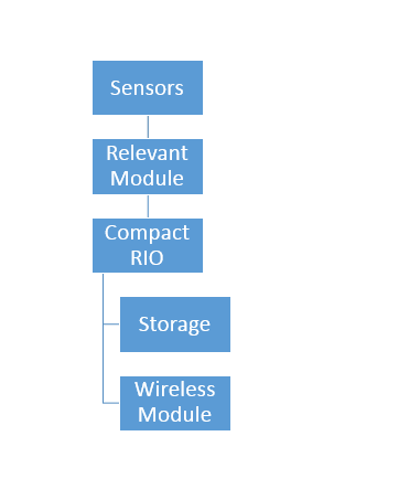
Figure 4 - Block Diagram for CompactRIO
Building the model
Adams Car by MSC software is a very detail vehicle dynamics simulation software which will need some real world data from our car to calibrate it for furute simulations. A series of sensor nodes to gather data during testing is therefore required.

Figure 5 - Adams Car Representation of USM15
Strain Gauges
Strain gauging has previously been attempted in the team on the wing mounts of the 2014 car during the first implementation of an aerodynamic package. An inhouse PCB was made to accomplish this but it failed dramatically.
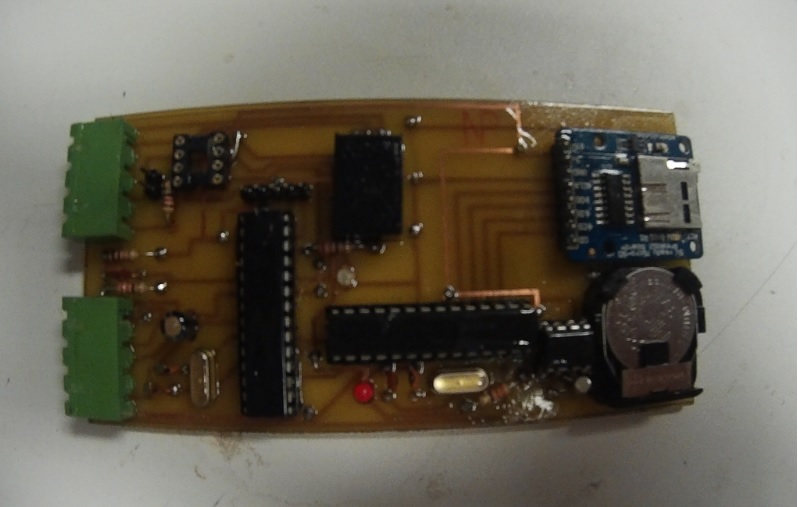
Figure 6 - Strain Gauge Signal Processing PCB from 2014
To improve the accuracy and reliability of this design, the NI-9235 strain gauge module was used to collect the data and the 24 bit resolution of the ADC is far superior to the previously used 10 bit setup. Calibrating the strain gauges will be done by straing gauging the push/pull rods of the suspension. Knowing the spring and tyre rates along with damper displacement using a linear potentiometer the effective force through the push rod can be calculated and then correlated with the output signal.
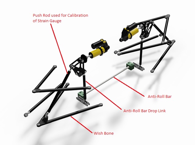
Figure 7 - Layout of Rear Suspension
After calibration various other components such as the wishbones, anti-roll bars and drive shafts will be strain gauged in a similar manner and will have three main benefits:
- The teams current analysis models will be consolidated with real time data
- Bearing size justification and new layouts of suspension can be designed based on known data
- Investiation to more advanced design concepts such as composite susepsnion members and fatigue analysis of drivetrain component.
Currently investigations into proper moutning of the strain gauges is being undertaken.

Figure 8 - Failed Strain Gauge Application Practice
Steering Angle and Driver Attitude
A series of sensors will also be used not only to validate designs but to help with the setup and testing of the car. A series of potentiometers to monitor throttle position and steering angle in addition to triple axes accelerometer, GPS and brake pressure will show how the car reacts to different driving situations and driver input. Correlating this data track side via Wi-Fi will be extremely useful for adapting the car from setup to setup in additon to lap times. As an example combining steering angle with lateral acceleration will allow a stability factor to be caluclated allowing the behaviour of the car to be characterised on entry during and exit of a corner.
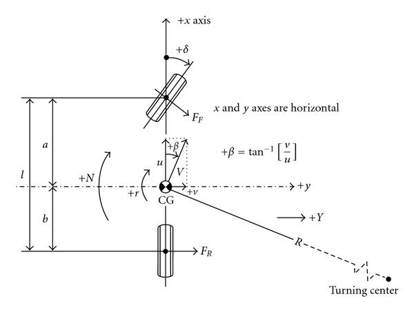
Firgure 9 - Bicycle Model of car which is the basis of the thought process and analysis of the car at testing (http://www.hindawi.com/journals/ijcgt/2009/952524/fig9/)
The slip angle of the car is defined as the angle between the direction of wheels and the direction in which the car is moving. If the car is not skidding, understeering or oversteering then the slip angle for the front and rear wheel will be identical. Therefore a trace comparing this theoretical steering angle with the actual steering angle along with lateral ecceleration and longituidinal velocity can characterise the stability of the car. In additon, monitoring the drivers inputs from braking and acceleration can also have an affect on setup changes and advice given to the driver.
Figure 10 - Brake Pressure Sensor on Master Cyclinder in Braking System
Tyre Temperature Sensors
Measuring the temperature across the surface fo the tyre will allow development of knowledge in the testing and setup phases, design and tyre choice phase as well as adding the the requirements of the Adams Car Model. Knowing the temperature distribution across the tyre in different situations allows the team to justify wheel camber setup to distribute the temperature evently across the tyre optimising tyre life over and endurance event. Monitoring the the temperture in realtion to the stability factor mentioned inthe previous section will allow the team to justify staying with the soft compound Hoosier LCO tyre which is known to over heat during long running but will work better in short events whereas a harder compound tyre such as the R25B by Hoosier may take longer to get to operating temperature but the stability over the whole event may be higher.
Figure 11 - Tyre Temperature Sensor
Level of Completion and Progress
Currently the team has jsut finished building the car with inital running completed succesfully. The data aquisition system is still in its own testing and construction stages while the basic running of the car and driver training is underway. Complettion of the design will be complete by the end of June to start initial data gathering before the cars first competitive outing at Formula Student UK at Silverstone. Testing will contiunue then continue through the season continually developing the Adams Car models.
Why LabVIEW ?
Due to the limited time and cost of testing reliability of the system is crutial and comparing to the teams previous attempts to create a realiable system National Instruments equipment is a definite improvement. The ease of use of the different modules makes adapting the system far easier and the very intuitive user interface of labVIEW makes utilisation and trouble shooting of problems far easier. The use of the specific equipment for this project make them applicable to far more projects than just data aquisition and monitoring and can be applied to a number of projects in the team for years to come benefiting not only the performnace of the car but the performance and skillset of the team members after graduation.
Conclusions
The aim of the project is to allow the team to develop a much deeper understanding of how the 2016 car will behave to implement far more extreme design changes to improve the dynamic performance of the team. This is being acheived this year via a data aquisition system and thorough testing to build computer simulations to implement these new designs. In addition training the team in the use of LabVIEW and other National Instruments equipment allows the team to develop further as a whole allowing for more advanced projects to be undertaken and also expanding the knowledge of the team members.
