Introduction to FPGA Vision Using the NI Vision Development Module
Overview
With FPGA technology and the NI Vision Development Module, you can perform high-speed field-programmable gate array (FPGA) processing on images acquired from cameras. FPGA processing is particularly useful in applications that require low latency between acquisition and the processed image. This document provides an overview of image processing on an FPGA, including typical use cases.
Contents
- Introduction to FPGA Programming
- Image Processing on the FPGA
- Vision Development Module FPGA Function Overview
- Use Cases for FPGA Vision
- Summary
- Related Links
Introduction to FPGA Programming
The NI LabVIEW FPGA Module is a natural extension of the LabVIEW graphical programming environment. You can perform complex FPGA programming without using low-level languages such as VHDL. If you are familiar with LabVIEW, transitioning to LabVIEW FPGA presents only a small learning curve. This can drastically reduce development time in applications that require FPGA programming, eliminating the need for custom hardware designs. Instead of programming in HDL, you create applications on the LabVIEW block diagram, and LabVIEW FPGA synthesizes the graphical code and deploys it to FPGA hardware.
Image Processing on the FPGA
Many image processing algorithms are inherently parallel and hence suitable for FPGA implementations. These algorithms which involve operations on pixels, lines, and regions of interest do not need high-level image information such as patterns. You can perform these functions on small regions of bits as well as on multiple regions of an image simultaneously. You can pass the image data to the FPGA in parallel and process that data concurrently, because a central processor is not required to process the data. The NI Vision Development Module contains over 50 image processing functions that can be used with the NI LabVIEW FPGA Module to process images on an FPGA. Some examples of image processing functions in Vision Development Module that are available for use on FPGAs are listed below:
Preprocessing
| Feature Extraction
Measurements
|
Vision Development Module FPGA Function Overview
When the Vision Development Module is installed with the NI LabVIEW FPGA Module, the Vision palette contains functions for use in FPGA image processing applications.
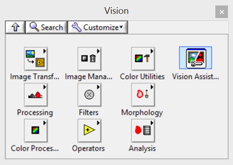
Figure 1. The Vision palette contains many functions for use in an FPGA image processing application.
The Vision palette contains image transfer VIs that can stream images between the FPGA and CPU. Section 2, Use Cases for FPGA Vision, discusses the various use cases and why it is sometimes necessary to transfer images to and from a CPU.
NI Vision Development Module includes the Vision Assistant Express VI, which can automatically generate LabVIEW FPGA image processing code with handshaking and synchronization, eliminating the need to write low-level synchronization code. You can also open Vision Assistant from a LabVIEW block diagram, or as a standalone program to create a LabVIEW project targeted to specific NI hardware.
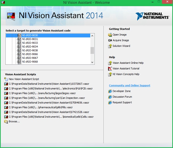
Figure 2. The Vision Assistant can be opened as a standalone program to generate code for a specific hardware target.
Once you choose a hardware target, Vision Assistant estimates the amount of FPGA target resources your image processing script requires. Vision Assistant then generates a LabVIEW project with a host VI and an FPGA VI for processing and transferring images.
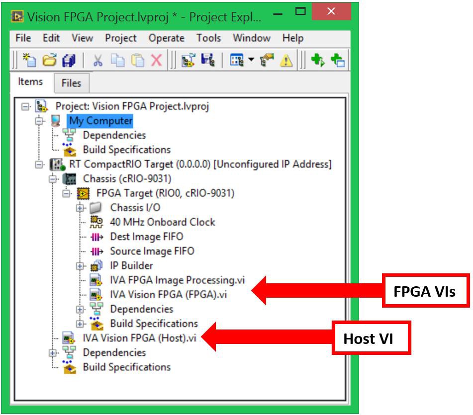
Figure 3. Once you finish creating your image processing script, Vision Assistant will generate a LabVIEW project that includes the hardware target, a host VI (if specified), and FPGA VIs for processing and transferring images.
Use Cases for FPGA Vision
Use Case 1: FPGA-Only Processing for High-Speed Control
FPGA image processing reduces the computational resources required for image analysis. Because the FPGA is a hardware resource, it frees the CPU to perform other operations. CPU intervention is not required to perform the analysis, which significantly reduces latency from processed image to control signal output. Figure 4 shows an example of how you can use the FPGA to offload resources from the CPU. In this case, the FPGA performs all of the image processing and generates an output signal. This results in minimum system latency allowing the control signal to be generated quickly.
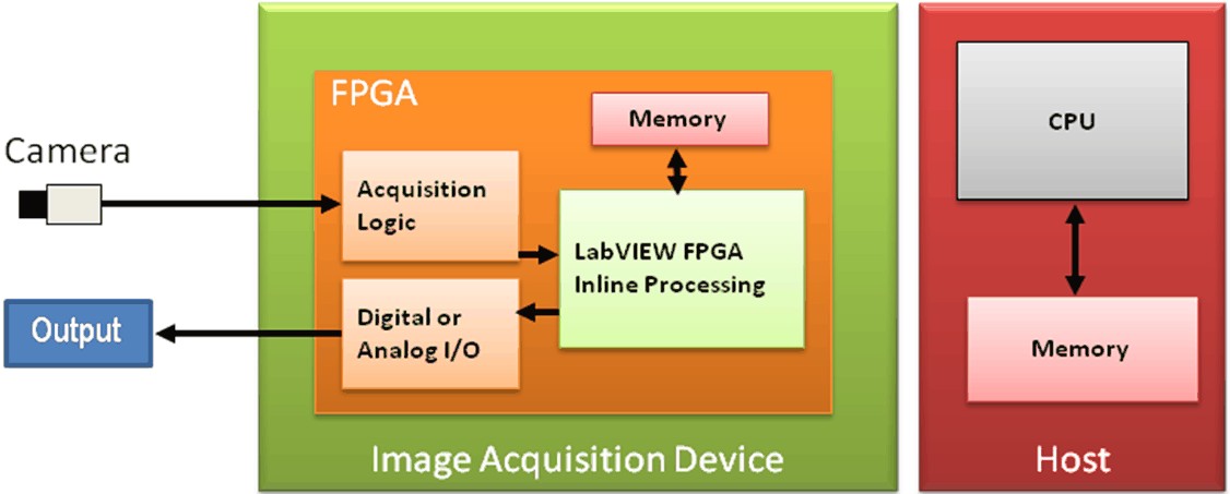
Figure 4. All processing is performed on the FPGA of the target. This frees the CPU to perform other tasks, thus minimizing system latency.
Examples of this use case include high-speed sorting, eye-tracking, and laser alignment. FPGA-only processing can be implemented on frame grabbers that place an FPGA directly in the path of the incoming image data. Two examples are the Camera Link Frame Grabber and the Camera Link Adapter Module.
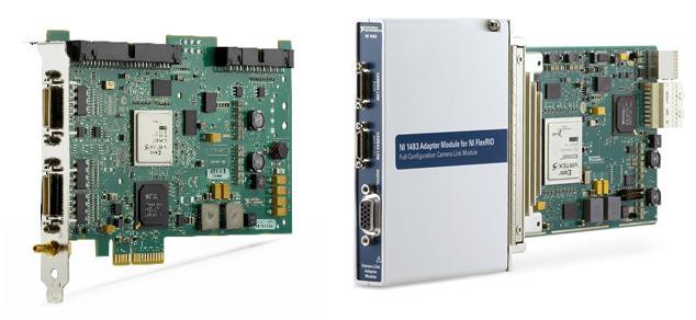
Figure 5. Both the Camera Link Frame Grabber and the Camera Link Adapter Module place an FPGA in the image path for onboard preprocessing and high-speed control applications.
Use Case 2: FPGA Preprocessing
You can perform additional processing by using a vision system processor with an FPGA. . Figure 6 shows how to preprocess with an FPGA while the CPU performs the more advanced processing algorithms. In this case, the FPGA performs bit-level processing such as filtering or edge detection. The preprocessed image is then sent to the CPU for image-level processing such as pattern recognition. System latency is still low in this case because the CPU has fewer functions to perform than it does in a traditional vision system.
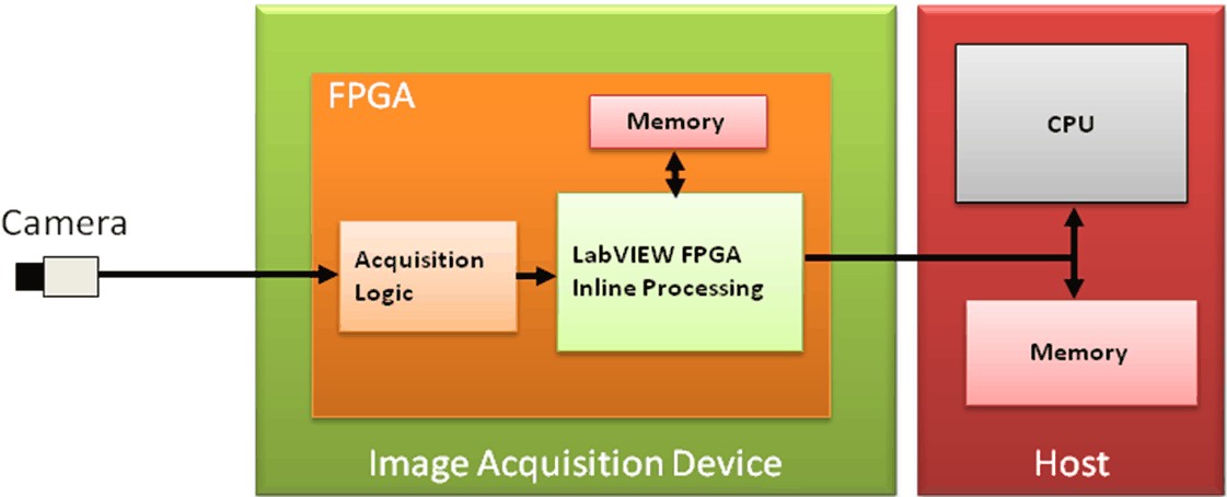
Figure 6. Image acquisition and preprocessing are performed on the FPGA and image data is then passed to the CPU. The CPU performs more complicated image analysis such as pattern matching and classification.
FPGA image processing is particularly useful in applications that require high-speed bit-level processing. The FPGA receives image data and processes individual bits using a high-speed onboard clock (up to 100 MHz clock rate). You perform data transfer and processing in hardware on a single clock cycle. You can break many vision algorithms into multiple iterative tasks and then break those tasks into parallel operations on the FPGA.
Examples where this type of architecture can be applied include surface and web inspection applications, and optical coherence tomography (OCT) applications. See Figure 5 for an example of two frame grabbers that are capable of FPGA preprocessing.
Use Case 3: FPGA Coprocessing
In some cases, you may have an image processing algorithm that consists of multiple steps. Some steps, such as thresholding, can be implemented on the FPGA. Other steps, such as pattern matching, may be better suited for the CPU. In cases like this, you can use an FPGA to offload work from the processor. As shown in Figure 7, The acquired image is sent to the CPU where it is streamed pixel by pixel to the FPGA for bit-level operations. As the pixels are processed on the FPGA, they may be sent back to the CPU for additional processing.
If your algorithm can be executed entirely on the FPGA, the pixels do not need to be sent back to the CPU. In this case, you can either use the FPGA to generate an output based on the image processing algorithm result, or send the processing results result back to the CPU for use in other parts of the system. An example of result data is a distance measurement, particle count, or any other result of an image processing step. FPGA co-processing decreases system latency by minimizing the number of functions performed by the CPU.
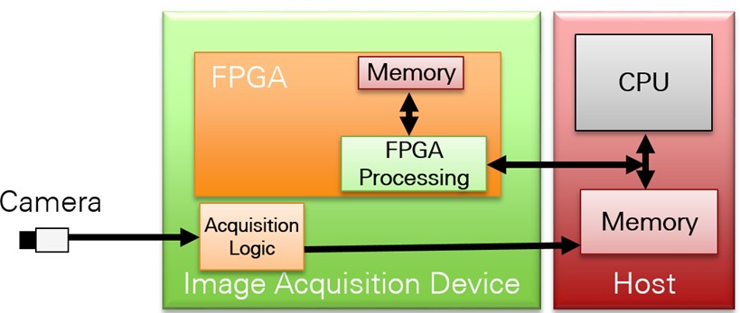
Figure 7. Image acquisition and preprocessing are performed on the FPGA. Image data is then passed to the CPU. The CPU performs more complicated image analysis such as pattern matching and classification.
FPGA co-processing can be implemented on CompactRIO Controllers as well as the Camera Link Frame Grabber and Camera Link Adapter Module.
An example of an application that benefits FPGA co-processing is particle counting for quality inspection. In this application, the particle counting can run on the FPGA to determine the number of particles as well as their size. This information can then be shared with the processor so that it can be displayed to the operator or used as an input to another process.
Summary
In summary, the high-speed operation and parallel nature of FPGAs allow them decrease image processing time thereby reducing system latency and increasing throughput. Additionally, FPGA image processing can allow controllers for systems such as high speed sorters to make decisions faster based off of acquired images. Also, thanks to innovations in embedded processing, 3D vision is now appearing in a variety of machine automation applications.