From Friday, April 19th (11:00 PM CDT) through Saturday, April 20th (2:00 PM CDT), 2024, ni.com will undergo system upgrades that may result in temporary service interruption.
We appreciate your patience as we improve our online experience.
From Friday, April 19th (11:00 PM CDT) through Saturday, April 20th (2:00 PM CDT), 2024, ni.com will undergo system upgrades that may result in temporary service interruption.
We appreciate your patience as we improve our online experience.
NI peer-to-peer (P2P) streaming technology uses PCI Express to enable direct, point-to-point transfers between multiple instruments without sending data through the host processor or memory. This enables devices in a system to share information without burdening other system resources. NI P2P technology is supported on particular models of PXI Express FlexRIO FPGA modules, FlexRIO coprocessor modules, oscilloscopes/digitizers, arbitrary waveform generators, vector signal analyzers, vector signal generators, vector signal transceivers, high-speed serial modules, and R Series devices.
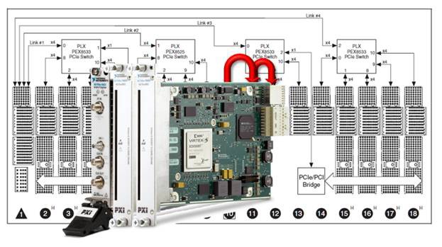
In the system depicted in Figure 1, a PXIe-5622 digitizer in a PXIe-1075 chassis uses peer-to-peer data streaming to send data directly to a PXIe-7966R FlexRIO FPGA module. The FPGA module then sends data to another FPGA module for additional processing. Because the chassis backplane switches provide direct links to the slots occupied by the modules, you do not need to transfer data through the host controller or use system resources such as the CPU or host memory.
Figure 1. A PXIe-5622 digitizer streams data to two PXI Express FlexRIO FPGA modules.
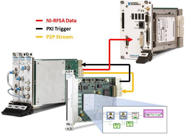
One common need in RF applications is a real-time frequency domain trigger. While most RF instruments trigger on a power level, this trigger is independent of frequency. However, with peer-to-peer data streaming and processing using the LabVIEW FPGA Module, you can create a frequency-domain trigger. In the application depicted in Figure 2, the PXIe-5663 vector signal analyzer uses peer-to-peer streaming to send data to the FlexRIO FPGA module, where it is windowed, converted to the frequency domain, and then compared against a mask. When the data exceeds this mask, the FPGA module asserts a digital trigger on the PXI backplane. Once the PXIe-5663 receives this trigger, it uses its normal acquisition memory to capture a record of data, including pretrigger samples. You can then access this record from the host through the NI-RFSA driver for additional processing or storage.
Figure 2. In this application, a FlexRIO FPGA module adds a frequency-domain trigger to the PXIe-5663 vector signal analyzer.
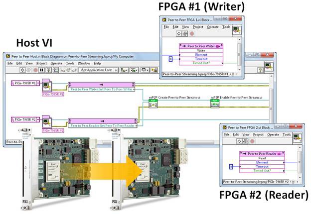
Programming peer-to-peer data streaming is greatly simplified by the NI-P2P driver. In the application depicted in Figure 3, FPGA No. 1 sends data directly to FPGA No. 2. In LabVIEW FPGA, simple peer-to-peer reader and writer nodes provide a first-in-first-out (FIFO) based interface for data exchange. These nodes are similar to DMA and local FPGA FIFOs. Before data exchange is possible, the host must connect the writer stream on FPGA No. 1 to the reader stream on FPGA No. 2 through the NI-RIO and NI-P2P APIs on the host (shown in Figure 3). Depending on the configuration, you need only one or two VIs to connect the peer-to-peer streams so that data exchange takes place.
Figure 3. Peer-to-peer streaming between two FlexRIO FPGA modules and the associated software.
With NI peer-to-peer technology, data streaming rates of up to 7 GB/s are possible in a single direction. Maximum throughput is dependent on the streaming modules, chassis, and, if the configuration warrants it, the controller. Generally, the lowest of these rates is the maximum possible P2P bandwidth.
Peer-to-peer transfers are designed to have a very low latency, but it will vary depending on the system configuration. When streaming only through FIFOs and the PCIe bus the typical latency is around 2-4 μs, though this will likely have an occasional spike into the tens of μs due to other bus traffic. When streaming from a digitizer we can usually expect around 5 μs of latency and when streaming to an arbitrary waveform generator around 10-20 μs of latency due to onboard buffering.
When streaming to/from devices with onboard signal processing, such as the PXIe-5622 digitizer, the additional filters and other processing can add up to hundreds of μs of latency. Finally, it is important to also consider the latency of the user code operating on the FlexRIO FPGA module when evaluating the performance of a system.
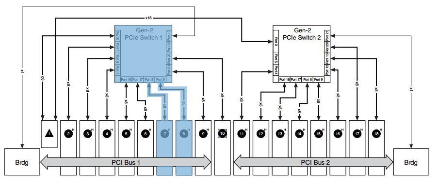
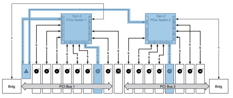
All data must pass through a chassis to stream from one module to another, so the chassis plays a critical role in determining bandwidth. The PCI Express switches on the chassis backplane route data through the chassis and provide the high-bandwidth point-to-point connections that enable peer-to-peer data streaming. When modules are in chassis slots that are directly connected to the same PCI Express switch, as in Figure 4, the bandwidth is dependent on the switch.
Figure 4. Module placement in the chassis routes all data through a single PCI Express switch.
Table 1 shows the maximum bandwidths of the PCI Express switches in a given chassis. This bandwidth is achievable through any two slots connected to the same switch, and multiple connections per switch are supported at the given rate. Chassis backplane architectures and bandwidths can be found in their respective specifications documents.
Chassis | Slots | Maximum Peer-to-Peer Rate (One-Way) |
|---|
PXIe-1062Q | 3-5 | Dependent on controller |
| PXIe-1065/1066DC | 7, 8 | Dependent on controller |
| PXIe-1065/1066DC | 9-14 | Just under 800 MB/s |
PXIe-1071 | All | Dependent on controller |
PXIe-1073 | All | >200 MB/s |
PXIe-1075 | All | >800 MB/s |
PXIe-1078 | 2, 3, 4 | Dependent on controller |
PXIe-1078 | 5-9 | >200 MB/s |
PXIe-1082Q | All | >800 MB/s |
| PXIe-1083 | All | 460 MB/s |
PXIe-1084 | All | 500 MB/s |
PXIe-1085 | All | 3.6 GB/s |
PXIe-1085 Gen 3 | All | 7.2 GB/s |
PXIe-1086 | All | 3.6 GB/s |
PXIe-1088 | 4,6,8 | Dependent on Controller |
PXIe-1088 | 2,3,5,7,9 | 500 MB/s |
| PXIe-1090 | All | 895 MB/s |
PXIe-1092 | All | 7.2 GB/s |
PXIe-1095 | All | 7.2 GB/s |
Table 1. PXI Express chassis P2P bandwidth
When modules in a P2P streaming system are not both connected to the same PCI Express switch on a chassis backplane, then data must pass through the host controller’s onboard switch or chipset, but not through its CPU or memory. This configuration is shown in Figure 5.
Figure 5. Module placement in the chassis routes data through the host controller.
Table 2 lists the maximum bandwidths of PCI Express switches or chipsets for a given controller. Note that this number represents the aggregate bandwidth through a certain segment into and out of the controller. If multiple peer-to-peer streams exist over these same segments, they must share bandwidth. Additionally, the chassis PCIe generation and number of lanes will also affect the maximum bandwidth. The values below assumes the chassis is of the same PCIe generation as the controller or newer.
| Controller | Maximum Rate Between Switches | Notes |
|---|---|---|
| PXIe-8135 | 3.4 GB/s | |
| PXIe-8133 | 1.6 GB/s | |
| PXIe-8130 | >600 MB/s | Limited by chipset |
| PXIe-8106 | >800 MB/s | Fourth link not supported (to/from rightmost switch on NI PXIe-1075 and NI PXIe-1082 chassis) |
| PXIe-8105 | Just under 800 MB/s | Limited by switch |
| PXIe-8101/8102/8108 | Not supported | P2P behind switches still works |
| PXIe-8301 | 6.4 GB/s (gen 3 x8) 3.2 GB/s (gen 3 x4) | |
| PXIe-8360/8370 | Just under 800 MB/s | Limited by switch |
| PXIe-8375 | >800 MB/s | |
| PXIe-8381 | 3.2 GB/s (gen 2 x8) 1.6 GB/s (gen 2 x4) | |
| PXIe-8398/8399 | 6.4 GB/s (gen 3 x8) 3.2 GB/s (gen 3 x4) | |
| PXIe-8821 | 500 MB/s | |
| PXIe-8840 | 2 GB/s | |
| PXIe-8861 | 6.4 GB/s (gen 3 x8) 3.2 GB/s (gen 3 x4) | |
| PXIe-8880/8881 | 6 GB/s (gen 3 x8) 3 GB/s (gen 3 x4) |
Table 2. PXI Express controller P2P bandwidth
Provided the chassis and controller configuration supports a certain bandwidth, the PXI Express modules themselves can determine the maximum bandwidth achievable. Below are benchmarks and configuration details for various P2P-capable devices.
PXIe-7976R, PXIe-7975R, PXIe-7972R, PXIe-7971R FlexRIO FPGA Modules: These PXI Express FlexRIO FPGA modules are capable of streaming data at 1.5 GB/s into or out of the module. The number of streams and their bandwidths are determined by the configuration and programming of the FPGA on the device. The PXIe-7976 uses a PCIe Gen 2 x8 interface, allowing it to stream up to 3.2 GB/s into or out of the module.
PXIe-7966R, PXIe-7965R, PXIe-7962R, PXIe-7961R FlexRIO FPGA Modules: These PXI Express FlexRIO FPGA modules are capable of streaming data at more than 800 MB/s into or out of the module. When streaming in both directions simultaneously, the FPGA modules can achieve rates of more than 700 MB/s per direction, or a more than 1.4 GB/s aggregate data rate. This data may consist of a single stream, or up to 16 separate streams, one for each DMA channel of the device. The number of streams and their bandwidths are determined by the configuration and programming of the FPGA on the device.
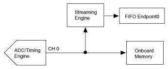
PXIe-5622 IF Digitizer: The PXIe-5622 is a 150 MS/s, 16-bit digitizer that can produce data at up to 300 MB/s. For peer-to-peer streaming, the digitizer has a single writer endpoint that is located on a parallel data path to the onboard memory. You can write the acquired data to this endpoint to stream to an FPGA target as well as send it to the host through onboard memory. A key feature of the PXIe-5622 is the onboard signal processing (OSP) with quadrature digital downconversion (DDC), which provides up to 60 MHz of IF bandwidth in the form of complex I/Q data at 75 MS/s, or 150 MB/s. In this mode, the samples are interleaved by sample in the peer-to-peer stream, with the I sample followed by the Q sample.
Figure 6. Peer-to-peer streaming with the PXIe-5622 IF digitizer
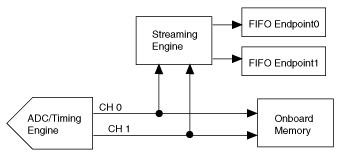
PXIe-5122 High-Resolution Digitizer: The PXIe-5122 is a 100 MS/s, two-channel, 14-bit digitizer that can produce data at up to 200 MB/s per channel per stream. For peer-to-peer streaming, the digitizer has two writer endpoints that are located on parallel data paths to the onboard memory. You can write acquired data to these endpoints as well as send them to the host through onboard memory.
Figure 7. Peer-to-peer streaming with the PXIe-5122 high-resolution digitizer
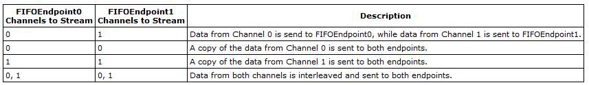
Examples of valid streaming configurations are shown in Table 3:
Table 3. Valid streaming configurations
Note that it is possible to configure the module to generate data at rates that exceed, for example, the PXI Express Gen 1 x4 bus bandwidth, which can result in data overflow. The last configuration of Table 3 results in 400 MB/s per stream when sampling at the full rate (800 MB/s total). If you also send data to the host PC, you exceed the bus bandwidth. Decreasing the digitizer sampling rate can prevent data overflow.
| Modules | Models | Maximum Peer-to-Peer Rate |
|---|
| Arbitrary Waveform Generators | ||
|---|---|---|
| PXIe-5450 (Rev. C and later) | >800 MB/s | |
| PXIe-5451 | >800 MB/s | |
| PXIe-5745 | 7 GB/s | |
| Scopes/Digitizers | ||
| PXIe-5122** | 800 MB/s | |
| PXIe-5160 | 800 MB/s | |
| PXIe-5162 | 800 MB/s | |
| PXIe-5164*** | 3.2 GB/s | |
| PXIe-5170*** | 3.2 GB/s | |
| PXIe-5171*** | 3.2 GB/s | |
| PXIe-5172*** | 3.2 GB/s | |
| PXIe-5622** | 800 MB/s | |
| PXIe-5624 | 3.2 GB/s | |
| PXIe-5763 | 7 GB/s | |
| PXIe-5764 | 7 GB/s | |
| PXIe-5774 | 7 GB/s | |
| PXIe-5775 | 7 GB/s | |
| RF Signal Analyzers | ||
| PXIe-5663* | ||
| PXIe-5663E* | ||
| PXIe-5665* | ||
| PXIe-5667 | ||
| PXIe-5668R | ||
| RF Signal Generators | ||
| PXIe-5673* | ||
| PXIe-5673E* | ||
| RF Vector Signal Transceivers | ||
| PXIe-5644R*** | ||
| PXIe-5645R*** | ||
| PXIe-5646R*** | ||
| PXIe-5840*** | ||
| FlexRIO FPGA Modules | ||
| PXIe-7961R | >800 MB/s | |
| PXIe-7962R | >800 MB/s | |
| PXIe-7965R | >800 MB/s | |
| PXIe-7966R | >800 MB/s | |
| PXIe-7971R | 1.5 GB/s | |
| PXIe-7972R | 1.5 GB/s | |
| PXIe-7975R | 1.5 GB/s | |
| PXIe-7976R | 3.2 GB/s | |
| FlexRIO Coprocessor Modules | ||
| PXIe-7911 | 7 GB/s | |
| PXIe-7912 | 7 GB/s | |
| PXIe-7915 | 7 GB/s | |
| High-Speed Serial Modules | ||
| PXIe-6591R | 3.2 GB/s | |
| PXIe-6592R | 3.2 GB/s | |
| PXIe-7902 | 3.2 GB/s | |
| NI R Series Devices | ||
| PXIe-7820R | 500 MB/s | |
| PXIe-7821R | 500 MB/s | |
| PXIe-7822R | 500 MB/s | |
| PXIe-7846R | 500 MB/s | |
| PXIe-7847R | 500 MB/s | |
| PXIe-7856R | 500 MB/s | |
| PXIe-7857R | 500 MB/s | |
| PXIe-7858R | 500 MB/s | |
| PXIe-7861 | 500 MB/s | |
| PXIe-7862 | 500 MB/s | |
| PXIe-7865 | 500 MB/s | |
| PXIe-7866 | 500 MB/s | |
| PXIe-7867 | 500 MB/s | |
| PXIe-7868 | 500 MB/s | |
| IF Transceivers | ||
| PXIe-5785 | 7 GB/s | |
Table 4. Maximum peer-to-peer bandwidth of the supported PXI Express Modules.
* The above mentioned RF Signal Analyzers are composed of three components: a RF downconverter, a local oscillator, and a digitizer. The digitizer is the component that does the P2P streaming. The digitizer that is used in these RF Signal Analyzers is the PXIe-5622. Similarly, the arbitrary waveform generator performs the P2P streaming for the RF Signal Generators.
** The PXIe-5122 and PXIe-5622 must have a current firmware version to enable peer-to-peer streaming, which was enabled as of NI-SCOPE 3.6. Follow the steps in the NI-SCOPE 3.6 Readme to learn how to update the firmware on your PXIe-5122 or PXIe-5622 device.
*** Software designed instruments may not support P2P streaming in their instrument drivers, but this capability is available through instrument driver FPGA extensions, and when programming with the devices’ Instrument Design Libraries. See the device-specific documentation for more details.
Peer-to-peer data streams are in the raw binary format, which does not include scaling or calibration. The normalization coefficients can be queried by NI-SCOPE and applied to calibrate the binary data without scaling to volts. The normalized data adheres to the following criteria, so you can later interpret the binary information or scale it to volts.
Note: The maximum and minimum binary values span the NI-SCOPE programmed vertical range (e.g. ±11 V) even if the user has specified ±10 V. This is to capture overshoots, even though the user set the range to be less than the overshoots.
Alternatively, you can query and apply the scaling coefficients to calibrate and scale the data in a single step. Refer to the High-Speed Digitizers Help for details.
The following list of NI hardware supports P2P streaming:
| Chassis | |
|---|---|
| PXIe-1062Q | |
| PXIe-1065/1066DC | |
| PXIe-1071 | |
| PXIe-1073 | |
| PXIe-1075 | |
| PXIe-1078 | |
| PXIe-1082 | |
| PXIe-1083 | |
| PXIe-1084 | |
| PXIe-1085 | |
| PXIe-1085 Gen 3 | |
| PXIe-1086 | |
| PXIe-1088 | |
| PXIe-1090 | |
| PXIe-1092 | |
| PXIe-1095 | |
| Controllers | |
| PXIe-8105 | |
| PXIe-8106 | |
| PXIe-8130 | |
| PXIe-8133 | |
| PXIe-8135 | |
| PXIe-8821 | |
| PXIe-8840 | |
| PXIe-8861 | |
| PXIe-8880/8881 | |
| Remote Controllers | |
| PXIe-8301 | |
| PXIe-8360 (PCIe-8361/8362) | |
| PXIe-8370 (PCIe-8371/8372) | |
| PXIe-PCIe-8375 | |
| PXIe-PCIe 8381 | |
| PXIe-PCIe 8398/8399 | |
| Arbitrary Waveform Generators | |
| PXIe-5450 (Rev. C and later) | |
| PXIe-5451 | |
| PXIe-5745 | |
| Scopes/Digitizers | |
| PXIe-5122** | |
| PXIe-5160 | |
| PXIe-5162 | |
| PXIe-5164*** | |
| PXIe-5170*** | |
| PXIe-5171*** | |
| PXIe-5172*** | |
| PXIe-5622** | |
| PXIe-5624R | |
| PXIe-5763 | |
| PXIe-5764 | |
| PXIe-5774 | |
| PXIe-5775 | |
| RF Signal Analyzers | |
| PXIe-5663* | |
| PXIe-5663E* | |
| PXIe-5665* | |
| PXIe-5667 | |
| PXIe-5668R | |
| RF Signal Generators | |
| PXIe-5673* | |
| PXIe-5673E* | |
| RF Vector Signal Transceivers | |
| PXIe-5644R*** | |
| PXIe-5645R*** | |
| PXIe-5646R*** | |
| PXIe-5840*** | |
| NI FlexRIO FPGA Modules | |
| PXIe-7961R | |
| PXIe-7962R | |
| PXIe-7965R | |
| PXIe-7966R | |
| PXIe-7971R | |
| PXIe-7972R | |
| PXIe-7975R | |
| PXIe-7976R | |
| NI FlexRIO Coprocessor Modules | |
| PXIe-7911 | |
| PXIe-7912 | |
| PXIe-7915 | |
| NI High-Speed Serial Modules | |
| PXIe-6591R | |
| PXIe-6592R | |
| PXIe-7902 | |
| NI R Series Devices | |
| PXIe-7820R | |
| PXIe-7821R | |
| PXIe-7822R | |
| PXIe-7846R | |
| PXIe-7847R | |
| PXIe-7856R | |
| PXIe-7857R | |
| PXIe-7858R | |
| PXIe-7861 | |
| PXIe-7862 | |
| PXIe-7865 | |
| PXIe-7866 | |
| PXIe-7867 | |
| PXIe-7868 | |
| IF Transceivers | |
| PXIe-5785 | |
Table 5. NI P2P supported hardware
* The above mentioned RF Signal Analyzers are composed of three components: a RF downconverter, a local oscillator, and a digitizer. The digitizer is the component that does the P2P streaming. The digitizer that is used in these RF Signal Analyzers is the PXIe-5622. Similarly, the arbitrary waveform generator performs the P2P streaming for the RF Signal Generators.
** The PXIe-5122 and PXIe-5622 must have a current firmware version to enable peer-to-peer streaming, which was enabled as of NI-SCOPE 3.6. Follow the steps in the NI-SCOPE 3.6 Readme to learn how to update the firmware on your PXIe-5122 or PXIe-5622 device.
*** Software designed instruments may not support P2P streaming in their instrument drivers, but this capability is available through instrument driver FPGA extensions, and when programming with the devices’ Instrument Design Libraries. See the device-specific documentation for more details.