Opening the Project
- Launch LabVIEW Communications System Design Suite 2.0 by selecting LabVIEW Communications 2.0 from the Start menu.
- Select the Projects tab.
- Select Application Frameworks.
- Select 802.11 Simulation v2.1 to launch the project.
- The script files of reference data interface are available in the following directory: <Project>\Testbenches\Reference Data Generator.
- Save the project and note the location to later use the given script files in GNU Octave to create the required test vectors.
Downloading the IEEE 802.11 Waveform Generator
The IEEE 802.11ac physical layer standard has several modes and options. To assist the readers of the specification, a waveform generator has been implemented by IEEE that can generate all modes described in the specification.
Download the seventh revision of the User guide for 802.11ac waveform generator from IEEE 802.11 Documents.
The code of the 802.11ac waveform generator running in GNU Octave is attached at the end of the User guide for 802.11ac waveform generator.
Testing Vector Generation Using the Reference Data Interface
Complete the following steps to create baseband test vectors. For more information about the reference data interface, refer to the last section of this document.
- The package ieee_tx11ac.zip attached in the User guide for 802.11ac waveform generator must be unzipped onto the following folder: <Project>\Testbenches\Reference Data Generation.
- Install GNU Octave 4.2.1 from www.gnu.org/software/octave/.
- Set the current directory of GNU Octave to the following folder: <Project>\Testbenches\Reference Data Generation\ieee_tx11ac as shown in Figure 1. You can use the GNU Octave function addpath to add the folder path, that is, addpath(<Project>\Testbenches\Reference Data Generation\ieee_tx11ac).
- With the folder ieee_tx11ac, run build_mex_11ac to compile the MEX files. The required MEX files will be created in the .mex format as shown in Figure 1.
- To run the above script, click the gear with yellow triangle as shown in Figure 1. You can ignore the following error:
econv.c: In function 'cenc':
econv.c:9:13: warning: type of 'bit_in' defaults to 'int'
static void cenc(bit_in) - Change the directory of GNU Octave to the following path: <Project>\Testbenches\Reference Data Generation, where the main function Test Vector Generator.m is located. It adds the required paths, sets the required configurations of all test cases, and calls the tx_11ac.m function of IEEE 802.11 Waveform Generator for every test case to create the baseband frame based on the given configuration.
- By running the Test Vector Generator.m function in the command window of GNU Octave, the test vectors of all pre-selected test cases will be generated and saved in the folder <Project>\Testbenches\Reference Data Generation\Test Vectors. You can ignore the warning that occurs during the reading of .mat files using the tx_11ac.m function of IEEE 802.11.
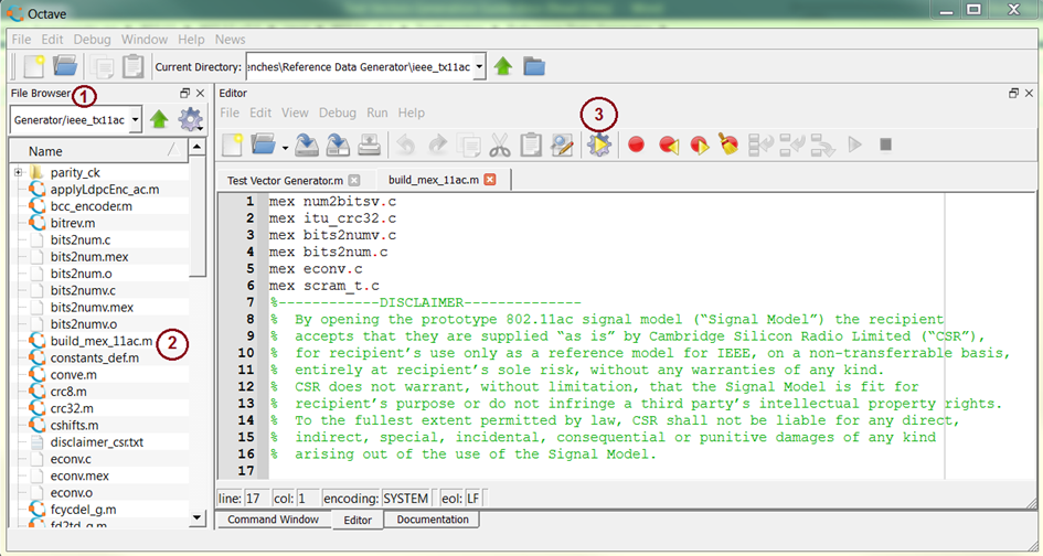
Figure 1. GNU Octave Front Panel
Reading the Test Vectors from LabVIEW Test Benches
Complete the following steps to read the test vectors from the test bench provided with 802.11 Application Framework 2.1 after data files generation and storing in the proper file format.
- Open the Testbenches folder in the 802.11 Simulation v2.1 project.
- As an example, open the TX Processing Simulation.gvi test bench.
- Select the Configuration & Status tab shown in Figure 2.
- Set the relative data path to the folder where the test vectors have been stored. The default relative path is Testbenches\Reference Data Generator\Test Vectors\IEEE_Tx11ac_Legacy_20MHz_80MSps_MCS0_3bytes_1frame.
- Read the description in the front panel of the test bench for more information about the signal processing tests that are executed in this test bench.
- Run the test bench.
Note: If the frame length is large and the modulation and coding scheme is small, the execution time is long. The numerical indicators Current Cycle and Number of Cycles under the Configuration & Status tab shown in Figure 2 show the executed number of cycles compared to the total number of required cycles. - If you are going to build another test bench that includes this test bench to run different test cases at once, disable the Boolean Control Is Relative Path shown in Figure 2. The absolute path will be provided by the new test bench.
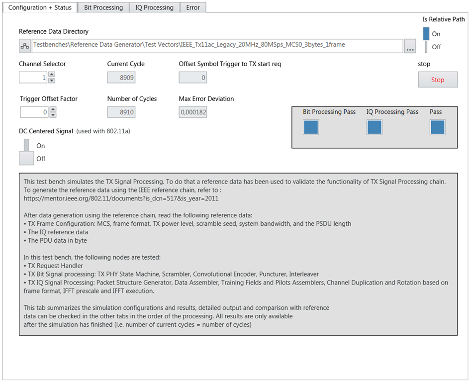
Figure 2. Front Panel of TX Processing Test Bench
Reference Data Interface
A script is created to use the IEEE 802.11 Waveform Generator to generate the 802.11ac TX signal for all modes and save the resulting baseband signal vectors in a proper format. It is sufficient to generate the test vectors only once. They will be then read from the LabVIEW code. The general file format has the following properties:
- ASCII files which are human readable
- CSV format with delimiter “;”
The following functions located in <Project>\Testbenches\Reference Data Generation are created to save the generated IEEE 802.11ac baseband signal for different modes in the proper format for LabVIEW test benches:
- High level functions/scripts (use structure ‘Tb’ structure as an interface):
- tbHelp.m: To be used as an overall documentation.
- tst_vec_gen_wr_file.m: To write the created CSV files based on the generated waveform using the ieee_tx11ac tool.
- tbFileHeader.m: Function for file header generation.
- tbSetResults.m: Script to copy values from local variables into ‘Tb’ structure.
- tbWriteDat.m: Function to write data into data files specified in ‘Tb’ structure (ASCII based and CSV).
- Low level functions:
- tbGenCfgCsv.m: Function for CSV file generation and writing.
- tbReadCsv.m: Function for reading CSV format-based TB configuration and reference data files.
- sat.m: Limits the input to a given bit width.
- outOfBitRange.m: Provides a flag if any element of the given vector exceeds range defined by bit width and symbol type.
- Test Vector Generator.m: The main function. By running this function in the command window of GNU Octave, the test vectors of all test cases will be generated and saved. It completes the following steps:
- Adds the ieee_tx11ac folder path of IEEE 802.11 test vector generator.
- Adds the Support path to the folder of the reference data interface functions. Those functions will write the test vectors in ASCII format to CSV files.
- Sets the required parameters for 106 test cases that have been generated. You can add more test cases to the script file with the required configurations. Those parameters are as follows:
- Frame Format: Three options need to be configured as shown in Table 1.
Table 1: Configuration Parameters of Test Cases
| Frame Format | Comment |
| Legacy | 802.11a |
| VHT | 802.11ac (Very High Throughput) |
| NONHT_DUP | non-High Throughput duplicate for some cases |
- System bandwidth
- Modulation and coding scheme (MCS)
- Number of bytes
- Calls the tx_11ac.m function of IEEE 802.11 to create the baseband frame based on the given configuration.
- Identifies the default path that the created test vectors will be saved in it. The default path is <Project>\Testbenches\Reference Data Generation\Test Vectors.
- Writes the reference files in the Test Vectors folder with a proper name. For example, if the test case has been configured with the configuration parameters presented in Table 2, the reference data folder name will be IEEE_Tx11ac_VHT_40MHz_80MSps_MCS8_1000bytes_1frame. Table 3 shows the description of all created files. Figure 3 shows the location of reference files in the TX chain. The presented numbers in Figure 3 are obtained from Table 3.
Table 2: Example of Configuration Parameters
| Configuration | Comments |
| Frame Format | VHT |
| Bandwidth | 40 MHz |
| Sampling rate | 80 MSps |
| MCS | 8 |
| Number of bytes | 1000 |
Table 3: Description of Files Names
| # in Figure 3 | File Name | Description |
| | cfg.str.csv | Contains the configuration information |
| 1. | pdu.data.csv | Contains PDU data |
| 2. | 1_sig_bits.csv | L-SIG field bits |
| 3. | l_sig_conv.csv | L-SIG field after the convolution and before the interleaver |
| 4. | l_sig_ilv.csv | L-SIG field after the interleaver and before the mapping |
| 5. | 1_siga_bits.csv | VHT-Signal-A field bits |
| 6. | v_siga_ilv.csv | VHT-Signal-A field after the interleaver |
| 7. | v_siga_fd.csv | VHT-Signal-A field at the input of IFFT |
| 8. | v_sigb_ilv.csv | VHT-Signal-B field after the interleaver |
| 9. | v_sigb_fd.csv | VHT-Signal-B field at the input of IFFT |
| 10. | v_dat_bit_info.csv | Data field in MAC bits |
| 11. | v_dat_bit_scramin.csv | Data field in bits before the scrambler |
| 12. | v_dat_bit_encodin.csv | Data field in bits before the encoder |
| 13. | v_dat_bit_encodout.csv | Data field in bits after the encoder |
| 14. | v_dat_bit_conv.csv | Data field in bits after the puncturing |
| 15. | v_dat_bit_ilv.csv | Data field in bits after the interleaver |
| 16. | v_dat_qam_pss.csv | Payload data which is in QAM symbols on the specified number of subcarriers. |
| 17. | v_dat_fd_psts.csf | Data field at the input of IFFT |
| 18. | sbb_str.csv | Baseband signal in time-domain |
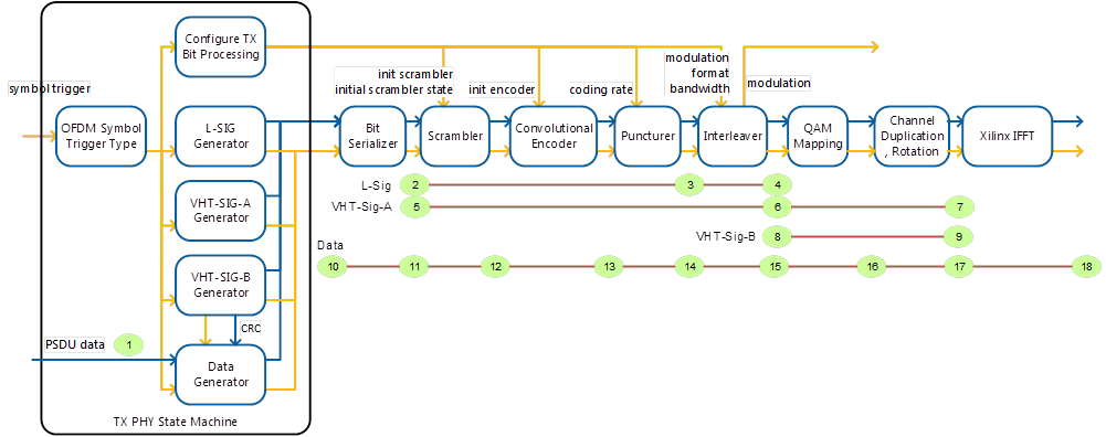
Figure 3. Location of Reference Data Files in the TX Chain, Numbers Based on Table 3