Using a Queued Message Handler in LabVIEW
Overview
The Queued Message Handler (QMH) template facilitates multiple sections of code running in parallel and sending data between them. Each section of code represents a task (e.g. acquiring data, logging data, user events) and is designed similarly to a state machine. Because of this design, you can divide each task into states.
The QMH template is a version of the Producer/Consumer design pattern, where the user interface (producer) produces messages and the tasks (consumers) consume them. However, in the QMH template, you also can produce messages from a consumer loop.
Contents
- Use Cases for Queued Message Handling
- LabVIEW QMH Walk-Through
- Example QMH Program
- Create a QMH Application from the LabVIEW Template
Use Cases for Queued Message Handling
The QMH template is useful for applications where multiple tasks occur in parallel, often at different rates. For example, consider an application that continuously acquires, logs, and displays two signals: an RS-232 signal and an analog signal. These signals occur at different rates, so the application must have two loops that run in parallel. In addition, each loop is divided into the following states:
- Initialize the data acquisition hardware
- Acquire data
- Log the acquired data to disk
- Display the acquired data in a waveform chart
- Set the hardware to a safe state
- Stop the data acquisition and shut down the hardware
The application requires a responsive user interface; that is, users should be able to click buttons even while the application is executing another command. Therefore, the application requires a third parallel loop that continuously monitors the front panel for events, such as the following commands:
- Start RS-232 acquisition
- Stop RS-232 acquisition
- Enable RS-232 logging
- Disable RS-232 logging
- Start analog data acquisition
- Stop analog data acquisition
- Enable analog data logging
- Disable analog data logging
The QMH template provides a starting point for writing this kind of application.
LabVIEW QMH Walk-Through
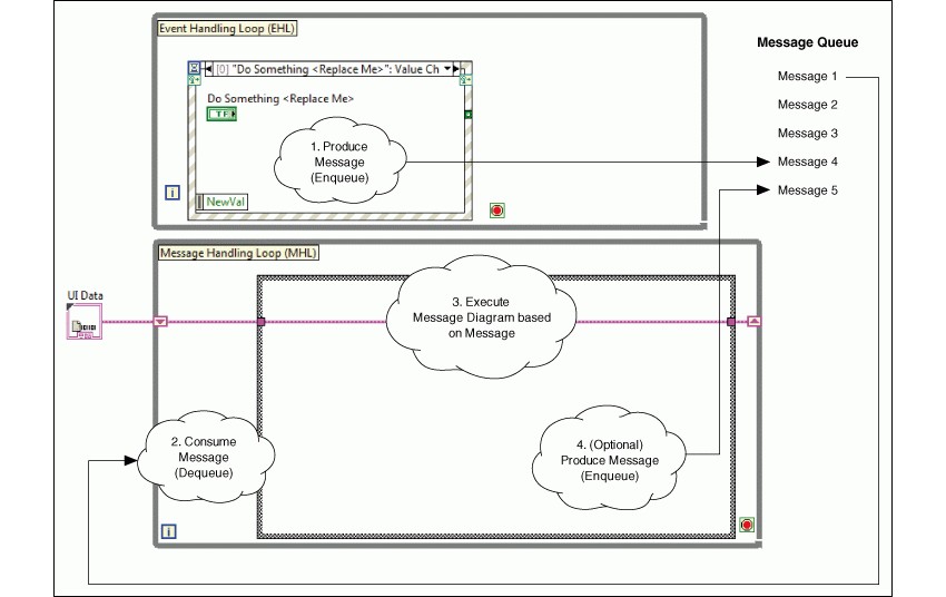
This template repeatedly executes the following steps:
- A user interacts with the front panel, causing the Event structure in the Event Handling Loop (EHL) to produce a message. LabVIEW stores the message in a queue.
- The Message Handling Loop (MHL) reads a message from the message queue, removing the message.
- The message is a string that matches one of the subdiagrams of the Case structure in the MHL. Therefore, reading the message causes the corresponding subdiagram of the Case structure to execute. This subdiagram is called a message diagram because it corresponds to a message.
- Optionally, the message diagram produces another message, storing it in the message queue.
Notes:
- The EHL is the producer loop. The MHL is the consumer loop. These loops run in parallel and are connected by the message queue, which facilitates communication between the loops.
- The message queue is a LabVIEW queue that stores messages for consumption. Because the EHL sends messages to this queue and not directly to the MHL, the EHL can produce messages while the MHL is not consuming them. Each message queue belongs to a single MHL.
- Every iteration of the MHL reads the oldest message in the message queue and then executes the corresponding message diagram. Although the MHL primarily consumes messages, it also can produce them.
- Your application can have multiple MHLs. Each MHL corresponds to a task the application performs, such as acquiring or logging data.
- Notice the UI Data cluster in the above diagram. This cluster is data that each message diagram in an MHL can access and modify. In this template, the cluster is defined as a typedef, UI Data.ctl. Each typedef belongs to a single MHL.
Example QMH Program
Refer to the Continuous Measurement and Logging sample project for an example of adapting the QMH template to a measurement application.
- Launch LabVIEW and select Create Project. From the Create Project dialog, launch the Continuous Measurement and Logging sample project.
- In the Project Explorer window, open and run Main.vi.
- Click the front panel controls and watch the Display indicator update.
- Review the block diagram. Notice the Event Handling Loop, Message Handling Loop, and interactions between the tasks.
- Use Highlight Execution to watch the flow of data and messages sent between the block diagram loops.
Create a QMH Application from the LabVIEW Template
LabVIEW includes a template project for this architecture which can be found by launching LabVIEW >> select Create Project >> Templates >> Queued Message Handler. This template includes one Event Handling Loop and one Message Handling Loop by default. You can update the template to fit your needs by following the tutorials in the table below.
Determining Your Needs
The following table summarizes the design decisions you must make when modifying this template.
Design Decision | Example | Tutorial |
|---|---|---|
You need to determine how many MHLs to add. Each MHL defines a task that executes in parallel with other tasks. | You have an application that acquires data and, in parallel, logs this data to disk. | Create a Message Handling Loop in LabVIEW Queued Message Handler Template |
For each MHL, you need to determine what message diagrams to add. | You want to separate the data acquisition task into three states: Initialize, Acquire Data, and Exit. Therefore, create these message diagrams in the MHL that acquires data. | Create a Message Diagram in LabVIEW Queued Message Handler Template |
You must determine what data the message diagrams of an MHL need. | Each message diagram of the data acquisition MHL needs access to a hardware reference. The Initialize message diagram needs to open this reference, the Acquire Data diagram uses this reference to acquire data, and the Exit message diagram closes the reference. | Defining Data that a Message Handling Loop Needs section in Create a Message Diagram in LabVIEW Queued Message Handler Template |
You need to determine when to execute each message diagram. A message diagram executes after its MHL receives the appropriate message. Therefore, you need to determine when to send each message to the MHL. You can send a message from a front panel control or from a message diagram. | You want to add a button that sends the Initialize message to the data acquisition MHL. | Send a Message to a Message Handling Loop in LabVIEW Queued Message Handler Template |
You need to determine if you want the Exit message to stop each MHL. The Dequeue Message VI uses this message because it is able to shut down an MHL. | You want each MHL to shut down when it receives the Stop message instead of the Exit message. | Send a Message that Stops the MHL section in Send a Message to a Message Handling Loop in LabVIEW Queued Message Handler Template |
When reading messages from the message queue, you need to determine if you want to ignore any specific errors. | When reading messages from the message queue, you want to ignore network timeout errors. | Handle Errors and Unrecognized Messages in LabVIEW Queued Message Handler Template |