Required Software
| Product | Software |
| MapleSoft Software |
- MapleSim3
- MapleSim3 Connector for LabVIEW and Veristand Software
|
| National Instruments Software |
- Simulation Interface Toolkit
|
| C++ Compiler |
|
| Mean-Value Internal Combustion Engine Model with MapleSim |
- http://www.maplesoft.com/engine_model/
|
Software Installation
Navigate to the MapleSoft download page for the Mean-Value Internal Combustion Engine Model with MapleSim. Download the MapleSim Model and the PDF. Insure that MapleSim3, MapleSim 3 Connector for LabVIEW and Veristand, the LabVIEW Simulation Interface Toolkit and Microsoft Visual Studios are installed.
Step-by-Step Creating a Model DLL
I. Model Preparation
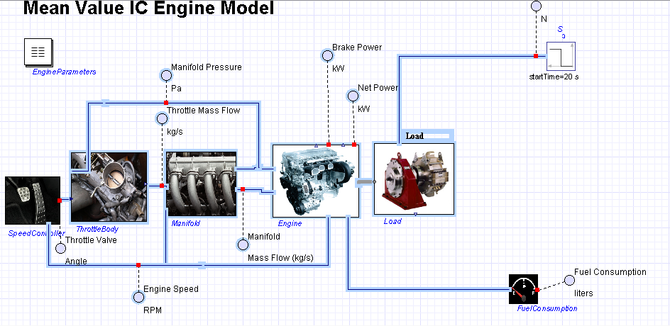
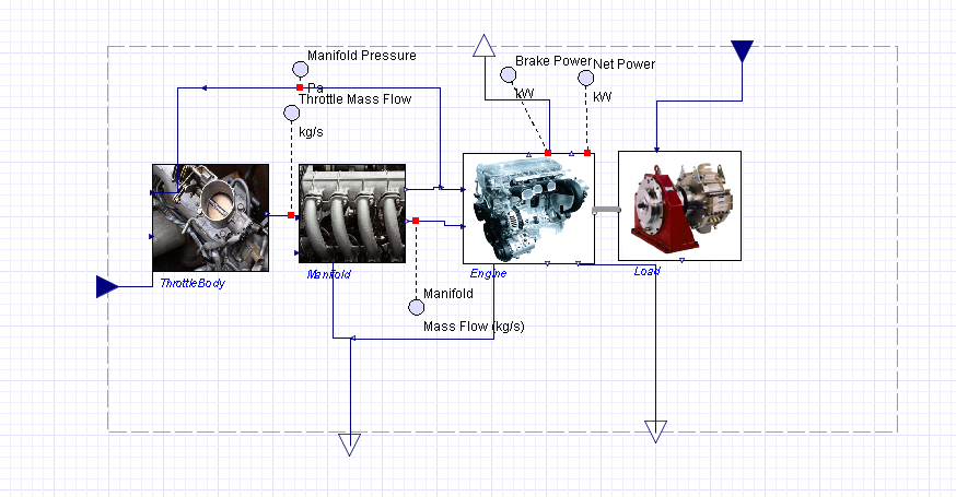
- Begin by Opening the MeanValueEngine.msim that you downloaded from MapleSoft.

- We will start by creating a subsystem that we want to make into a dll. Select everything that you would like to put into the subsystem.
For this subsystem, include the Throttle Body, Manifold, Engine and Load.
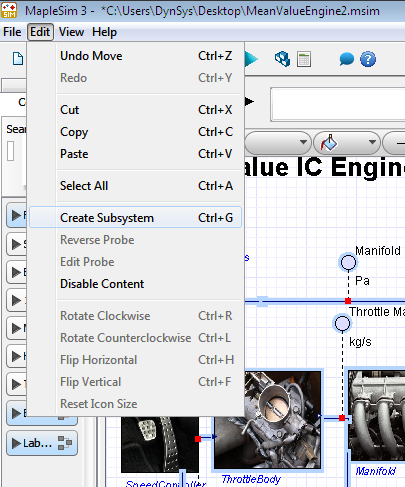
- Select Edit >> Create Subsystem .
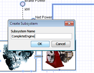
- Enter CompleteEngine into Subsystem Name .
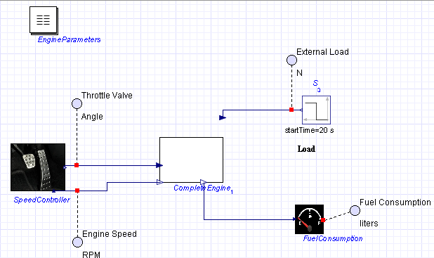
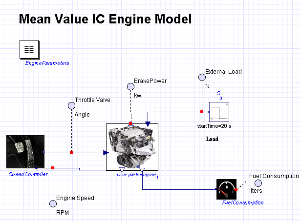
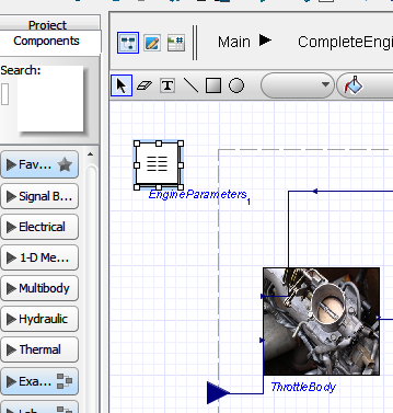
- Organize the Main Diagram.
- Go into the CompleteEngine subsystem and reorganize as appropriate.
a. Connect RealInput2 to the bounds of the subsystem.
b. Expand the bounds of the subystem.
c. Reorient the input and output terminals.
d. Drag the BrakePower output to the bounds of the sub-diagram. This will automatically create an output node.
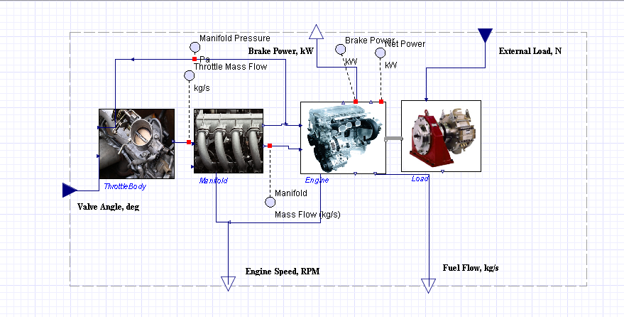
- Label the input and output terminals for Brake Power, External Load, Valve Angle, Engine Speed, and Fuel Flow using the text tool.
- Rename the inputs and outputs for the CompleteEngine subsystem by selecting them in the ModelTree, right clicking the port, and selecting Rename .
a. Do this for RealInput1, RealOutput5, RealOutput6 and realInput2.
b. Rename them AngleInput, FuelFlowOutput, EngineSpeedOutput, LoadInput and BrakePowerOutput respectively.
- Add a picture to represent the CompleteEngine in the Main diagram.
- Go to the Icon Tool
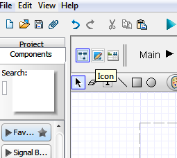
- Select the outline of the subsystem
- Select the drawing fill tool
- Select Browse
- Select the picture you would like to insert into the diagram and select Open
- Go back to the diagram by selecting the diagram tool.
- Navigate to the Main subsystem and add a probe for the BrakePowerOutput. Name it BrakePower with units kw. You can do this by right clicking the output of BrakePower and selecting attach probe.
Define System Parameters
-
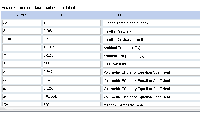
- Copy the Engine Parameters list from the Main subsystem and paste it into the CompleteEngine subsystem.
-
- Select Parameter Editor
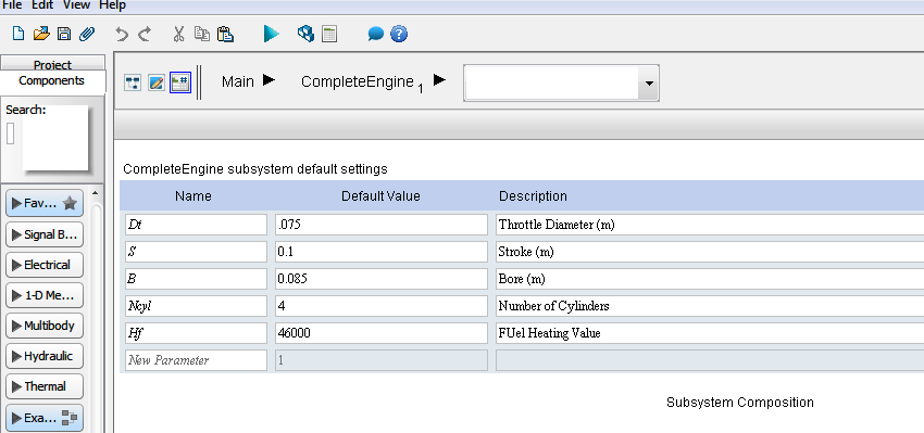
- Add inputs for throttle diameter, stroke, bore, number of cylinders and the fuel internal heat value with the values seen in the chart below.
- Delete the parameters from the local Engine Parameters Block on the Main subsystem by double clicking on the parameters block, finding the values for Dt, S, B, Ncyl, and HF and selecting delete.
- The values will also be available in the Parameter Inspector for the CompleteEngine Subsystem.
Model Generation for Veristand
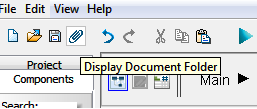
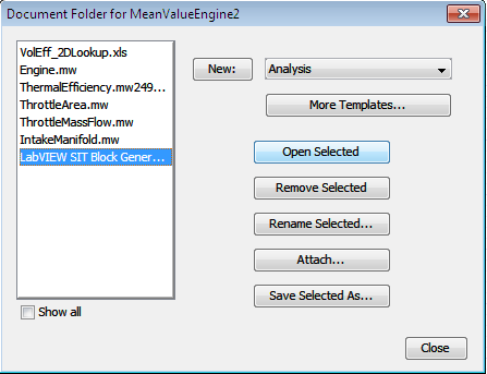
- To generate a dll based on the model that you currently have, select the Display Document Folder tool that appears as a paperclip in the top left hand corner of the screen.
- Select the drop down list next to the New: Button and select LabVIEW SIT Block Generation .
-
- Select the New Button to move the selected item to the column on the left
- Select the item that you just added and then click on Open Selected .
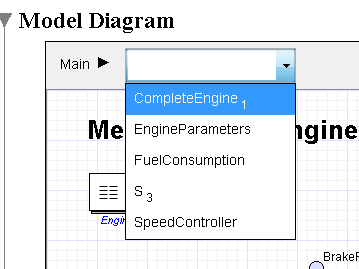
- In the Model Diagram Section Select CompleteEngine to link to the correct subsystem.
- Select the System Update Button to update the inputs and outputs for the template.
- Keep Both selected under Input Setting and Euler (1st order Forward Euler) under Solver Setting.
- Under Setting Parameters move all 5 components under Substituted Parameters to the block Parameters list.
- Leave the Advanced Code Generation Settings in their default state for this system. They include the Code Optimization Options and DAE Constraint Option.
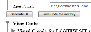
- Select the default directory that SIT was installed to on your computer along with the SIT version. As well select the default Directory that you want to save the dll to under Set Default Directory.
- Select Generate DLL, Maple will then generate the C code for the model and store it into the defined folder.

You are now able to use the DLL generated to import into Veristand on a Real-Time System
OS and Visual Studios Caveats
If using Microsoft Windows 7 and Visual Studios 2005. Install the Service Pack 1 for VS2005 as well as the VS Service Pack for Vista.