From Friday, April 19th (11:00 PM CDT) through Saturday, April 20th (2:00 PM CDT), 2024, ni.com will undergo system upgrades that may result in temporary service interruption.
We appreciate your patience as we improve our online experience.
From Friday, April 19th (11:00 PM CDT) through Saturday, April 20th (2:00 PM CDT), 2024, ni.com will undergo system upgrades that may result in temporary service interruption.
We appreciate your patience as we improve our online experience.
NI offers multiple options for connecting the single-ended digital pattern instruments and digital waveform instruments to your device under test (DUT). Each option is designed for controlled-impedance 50 Ω traces and matched trace lengths.
SHC68-C68-D4 Cable
NI recommends that you use the NI SHC68-C68-D4 shielded cable for connections to your instrument. This cable is designed specifically for the custom pinout of the VHDCI connector on these devices, and it provides 50 Ω coaxial transmission lines for each signal.
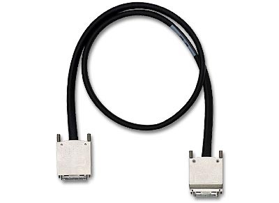
Figure 1: SHC68-C68-D4 Cable
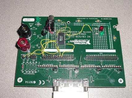
NI CB- 2162
The NI CB-2162 is a connector block and prototyping board for single-ended digital pattern instruments and digital waveform instruments. The NI CB-2162 provides an easy way to do the following tasks:
• Terminate digital I/O (DIO) and control channels
• Connect with other devices for testing and debugging
• Develop and interface to prototype circuits
• Probe DIO and control channels
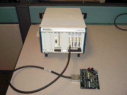
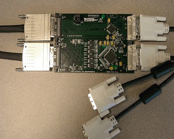
In Figure 2, the single-ended digital waveform instrument is connected to the NI CB-2162 using the older NI SHC68-C68-D2 cable. In this figure, the DUT was placed directly on the prototyping area of the CB-2162 and wired to the header pins. Additionally, the header pins can be used to cable to an external DUT interface board.
NI SMB-2163
The NI SMB-2163 is a breakout box for single-ended digital pattern instruments and digital waveform instruments. The NI SMB-2163 provides an easy way to connect to other devices for testing and debugging by routing every DIO and control channel on a separate SMB coaxial connector.
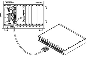
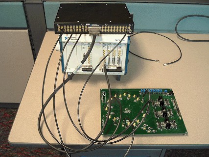
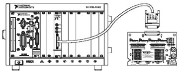
Figure 3: Connecting an NI SMB-2163 to a Digital Waveform Generator/Analyzer
In Figure 3, the single-ended digital waveform instrument is connected to the NI SMB-2163 through the older SHC68-C68-D2 cable. The connection between the NI SMB-2163 and the DUT is made using coaxial SMB cables (as shown).
Custom PCB
If a solution is not viable with any of the previous accessories, creating a custom printed circuit board (PCB) is the last option for connecting the single-ended digital pattern instrument or digital waveform instrument to the DUT. This option allows you to customize the interface to effectively meet the requirements of your DUT.
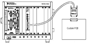
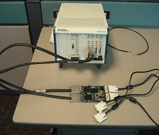
Figure 4: Connecting a Custom PCB to a Digital Waveform Instrument
In Figure 4, the single-ended digital waveform instrument is connected to the VHDCI connector on the custom PCB using the older NI SHC68-C68-D2 cable. The connection between the VHDCI connector and the DUT is routed on the custom PCB.
Using a custom PCB will be described in more detail in the following section.
There are several factors to consider when you choose to build a custom PCB.
Connector Pinout
Refer to your instrument help for more information regarding the specific pinout for the connector on your instrument. For example, figures 5 and 6 show the connector pinouts for the PXI/PXIe-654X and PXI-6551/6552.
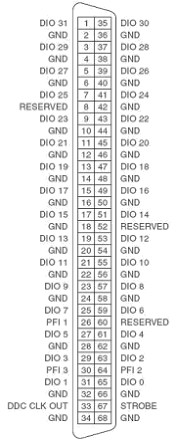
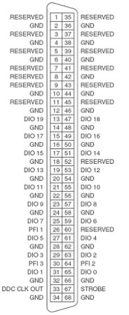
Figure 6: PXI-6551/6552 Pinout
Choosing a Connector
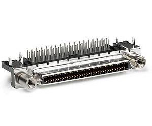
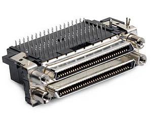
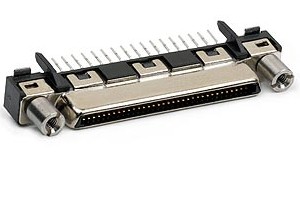
There are four common styles of VHDCI connectors. Table 1 shows pictures of the VHDCI connectors that are available from NI. For more information, please visit the following article: NI HSDIO Device Custom Cables, Replacement Connectors, and Screws.
|
|
|
| Right-Angle VHDCI Connector | Right-Angle Dual-Stack VHDCI Connector | Vertical Mount VHDCI Connector |
Layout Considerations
The following sections describe steps that should be followed when creating a custom PCB to interface with a single-ended digital pattern instrument or digital waveform instrument.
Digital instruments produce high-quality signals with fast edge rates and thus require special considerations when routing signals to maintain signal integrity. In addition to following standard design guidelines, be sure to use the following guidelines in your design:
· Route all traces with 50 Ω impedance; this maintains the matched 50 Ω system.
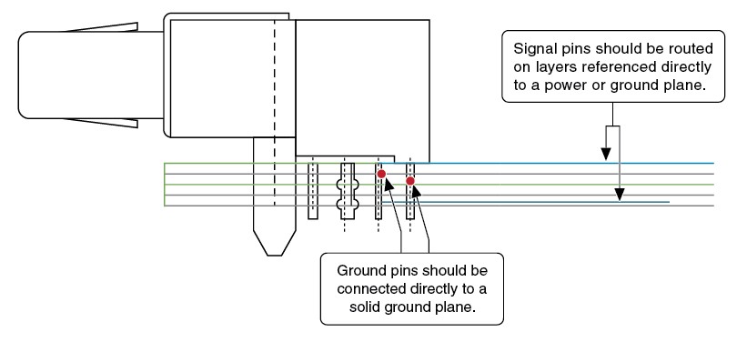
· Route ground pins directly into a solid ground plane.
· Reference all routed signals to at least one solid ground or power plane.
· Route all traces with sufficient trace spacing to maintain low crosstalk (Refer to Figure 7).
· Match all trace delays to maintain low skew (Refer to Figure 7).
· Trace delay depends on physical length and dielectric constant of the PCB. Therefore, surface traces will need different physical lengths than internal stripline traces.
· Maintain all ground return paths.
The ground pin connections to the ground plane are critical for keeping crosstalk low. Crosstalk is induced by the magnetic field that is produced when a signal is traveling along a trace. When two signals share a ground return path, the magnetic field from one signal is induced on the second signal, causing noise.
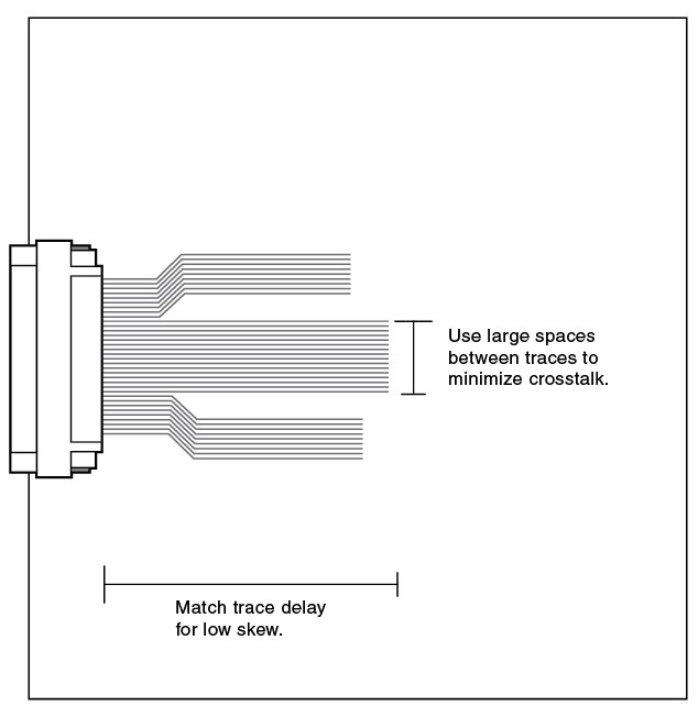
Figure 7: Trace Guidelines
Figure 8: Signal and Ground Routing