Turn on a DC Computer Fan using a Solid-State Relay, myDAQ, and LabVIEW
- Subscribe to RSS Feed
- Mark as New
- Mark as Read
- Bookmark
- Subscribe
- Printer Friendly Page
- Report to a Moderator
Code and Documents
Attachment
Overview
This document explains using a low-cost (3.3 V) solid-state relay to control a 12VDC Fan with your National Instruments myDAQ in LabVIEW. The digital output will be generated on the myDAQ digital line using the DAQ Assistant that is installed into LabVIEW with the NI DAQmx driver.
Objective:
Use a 3.3V Controlled Solid State Relay to turn on a 12V DC Computer Case Fan using a digital output line on your myDAQ.
Tip! Be sure to purchase a relay that is activated with a 3.3V signal - NI myDAQ outputs a 3.3V digital signal. Also, some relays require more current than others - you can output two lines in parallel to the relay to add more current.
Background:
A relay is a means of completing/closing a higher voltage circuit with a low-voltage, low-current signal, similar to controlling a high-pressure hydraulic line on a tractor with a low pressure control line within the cab. This technology allows microcontrollers and other low voltage devices to control motors and fan in industrial and robotic applications. A solid-state relay (SSR) allows for an even lower current controlling signal, such as the DC output from the myDAQ. We can integrate a 12VDC power supply connected to a 12VDC computer case fan in series with the SSR to turn on the fan using the digital output of the myDAQ.

Figure 1: Omron Controlled Solid-State Relay and Antec 80mm 12VDC Case Fan
What You Need:
- NI myDAQ
- LabVIEW
- 3.3VDC Solid-State Relay (Purchased from newark.com for $4.22)
- Antec 80mm 12VDC Case Fan (Purchased from provantage.com for $1.79)
- 12VDC Power Supply
- Wire
- Breadboard
Wiring Instructions:
The Solid State Relay is wired in series with a 12VDC power supply and the 12VDC Case Fan to control when the circuit is closed or open. The SSR is also wired to the myDAQ Digital Output pin 0 and Digital Ground. This second connection is used to send a digital signal from the myDAQ device in order to open or close the fan/power supply circuit.
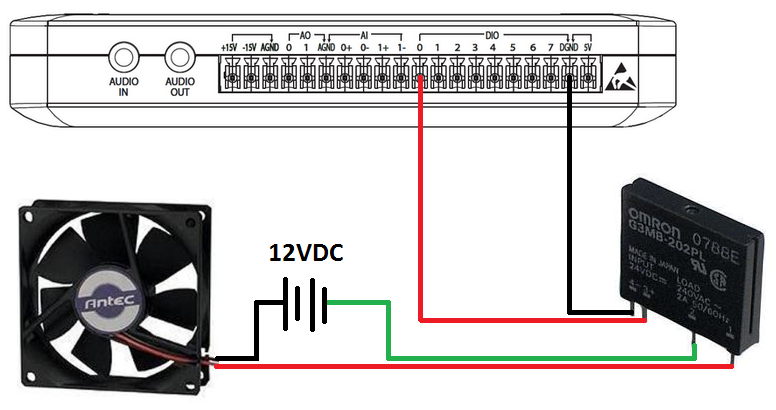
Figure 2: Wiring Diagram
LabVIEW User Interface:
The user interface we created has a Boolean push button switch to control the SSR to be open or closed, which will then turn the fan on or off.

Figure 3: LabVIEW Front Panel
Coding Strategy:
In LabVIEW we need to create a front panel Boolean array control to output a 5V digital signal on Line0 to our Solid-State Relay. This Boolean value is input into our DAQ Assistant which will output the corresponding value to the NI myDAQ digital line. In digital Boolean logic, a True corresponds to a 5V signal, and a False corresponds to a 0V signal. Therefore, a True will close the SSR, and complete the fan and power supply circuit, allowing power to flow to the fan.

Figure 4: Coding Block Diagram
The LabVIEW diagram looks very similar to the coding block diagram, except the SSR is not included.

Figure 5: LabVIEW 2009 Block Diagram
(The attached LabVIEW code snippet can be dragged-and-dropped to a LabVIEW block diagram, use attached PNG file. After locating the PNG file, just drag the file icon onto a blank block diagram, as if you were dragging the file onto your desktop.)
How It Works:
Inside the while loop on the left is the Boolean Array Control used to send a True or False to the SSR. The control is on the front panel, and can be seen to have only one element in the array. This is because the DAQ Assistant is setup to only output to one line. On the right is the DAQ Assistant. It’s configured to output a single value from the myDAQ Digital Port0/Line0 each time it executes. All of the code inside the While Loop continues to run until the Stop button is pressed on the front panel. The Wait VI (top left) delays execution of the while loop to every 100ms. Therefore the output rate is 10 samples per second, or 10 Hz. When the Stop button is pressed and the while loop is exited, a False is output to the line, opening the SSR and turning off the fan for safety.
In this VI the DAQ Assistant is configured for on-demand output on the digital channel. The following steps walk through the configuration of the DAQ Assistant from scratch:
- Be sure your myDAQ is plugged in
- Press Ctrl-Space to bring up the Quick Drop Window (takes a full minute to load on the first use)
- Search for DAQ Assistant and double click on it when it appears in the list
- Drop it on the Block diagram (white window)
- When the Create a New Express Task configuration pane appears, select
- Generate Signals
- Digital Output
- Line Output
- Dev 1 (NI myDAQ) *Note: If you have other NI hardware installed, the myDAQ will not be Dev1.
- port0/line0
- Finish
- Leave Timing Settings to
- 1 Sample (On Demand)
- Do not Invert Line
- Press OK

Figure 6: DAQ Assistance Resistance Configuration
*Note that sample time is set by the Wait VI and is set to sample 10 times per second (every 100ms) in this VI
Tips and Tricks
- You can modify the VI to log the data to file using a ‘Write To Spreadsheet File.vi’ express VI if you wish to save the data. Be sure to place it in the loop and be sure to append new data to the spreadsheet file.
- Use ‘From DDT’ to turn the blue Dynamic Data Type wire into an orange double precision number. This allows the data from the DAQ Assistant to be used with standard LabVIEW VIs.
- Use this document in conjunction with the Measure Temperature using 10kΩ Thermistor, NI myDAQ, and LabVIEW document to turn on the fan when a certain temperature threshold is met. You can use a comparison to output a true or false into the case structure if a value is greater than another number.
- If you add a lamp to provide heat to the thermistor and use the fan to cool the thermistor. This is effectively a thermostat, similar to the type found at home.
Related Links
Example code from the Example Code Exchange in the NI Community is licensed with the MIT license.
